Gas flowmeter

A gas flow meter and flow technology, which is applied in volume measurement, liquid/fluid solid measurement, flow/mass flow measurement, etc. It can solve the problems of unstable support of ultrasonic flow measurement unit and unstable flow measurement, etc.

Inactive Publication Date: 2016-10-12
PANASONIC INTELLECTUAL PROPERTY MANAGEMENT CO LTD
View PDF10 Cites 5 Cited by
  • Summary
  • Abstract
  • Description
  • Claims
  • Application Information

AI Technical Summary

Problems solved by technology

In this case, the support of the ultrasonic flow measurement unit becomes more unstable, and there is a problem that stable flow measurement cannot be performed (for example, refer to Patent Document 1).

Method used


Image

  • Gas flowmeter
  • Gas flowmeter
  • Gas flowmeter

Examples


Embodiment approach 1

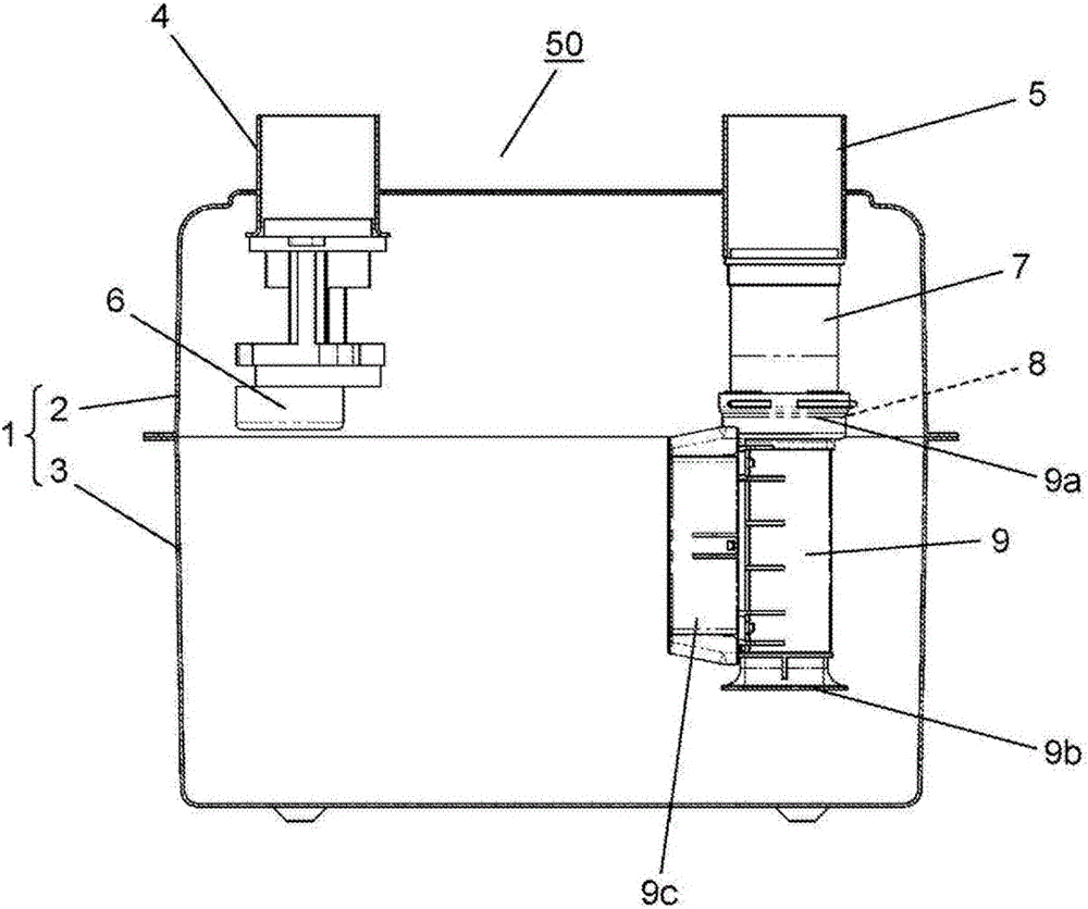
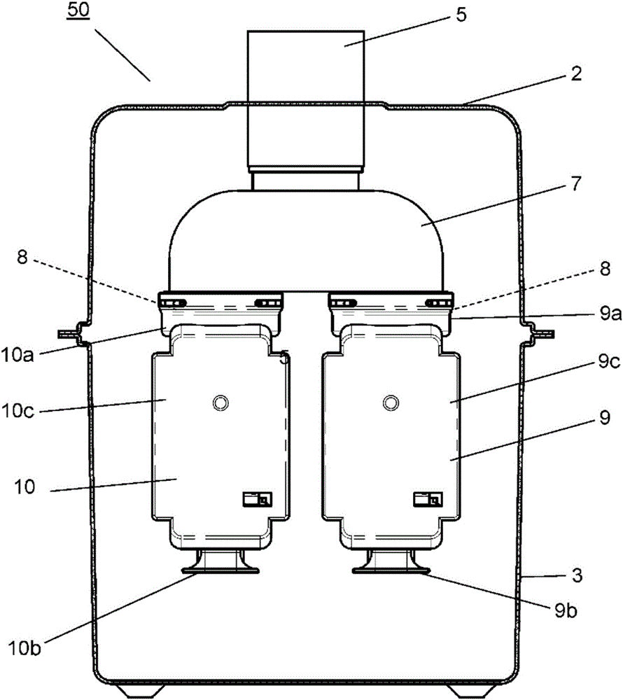
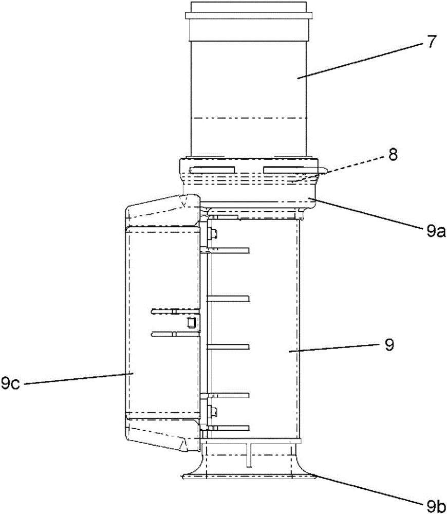
[0033] based on Figure 1 to Figure 5 Embodiment 1 of the present invention will be described. figure 1 It is a sectional view of the gas flow meter according to Embodiment 1 of the present invention. figure 2 is a cross-sectional view illustrating the same gas flowmeter, obtained from the same figure 1 Cross-sectional views viewed from different directions. image 3 It is a side view of the main part of the same gas flowmeter. Figure 4 It is a perspective view of the main part of the same gas flow meter. Figure 5 It is an exploded perspective view of the main parts of the same gas flowmeter.

[0034] The casing of the gas flow meter 50 is constituted by the device main body 1 . The device main body 1 includes an upper case 2 and a lower case 3 formed by pressing metal. The upper surface of the upper case 2 is provided with: an inlet 4 through which the fluid to be measured can be introduced into the device body 1; and an outlet 5 through which the fluid to be measu...

Embodiment approach 2

[0047] Next, use Figure 6 and Figure 7 A gas flow meter according to Embodiment 2 of the present invention will be described. Figure 6 It is a perspective view of main parts of the gas flow meter according to Embodiment 2 of the present invention. Figure 7 It is an exploded perspective view of the main parts of the same gas flowmeter. In addition, the description of the same structural elements, operations, and the like as those of the gas flowmeter 50 of Embodiment 1 is omitted.

[0048] In this embodiment, the cover body 9c of the flow measurement part 9 and the cover body 10c of the flow path member 10 are integrated to form the support member 12 connecting the flow measurement part 9 and the flow path member 10 . The flow measurement unit 9 and the flow path member 10 are connected by the support member 12 to be integrated, can be handled as a unit, and can improve operability. In addition, since the flow measurement part 9 in the state connected to the connection ...

Embodiment approach 3

[0052] Next, use Figure 8 and Figure 9 A gas flow meter according to Embodiment 3 of the present invention will be described. Figure 8 It is a sectional view of main parts of the gas flow meter according to Embodiment 3 of the present invention. Figure 9 It is a perspective view of the main part of the same gas flow meter. In addition, the description of the same structural elements, operations, and the like as those of the gas flowmeter 50 of Embodiment 1 is omitted.

[0053] In the present embodiment, the flow path member 13 has an adjustment valve 14 . The outflow port 13 a of the flow path member 13 is connected to the attachment portion 8 of the connection portion 7 , and the flow path member 13 is arranged vertically below the connection portion 7 with the inflow port 13 b facing downward.

[0054] The adjustment valve 14 has an operation part 15 operable from the outside. By operating the operation part 15 , the flow rate of the fluid to be measured in the flow...


PUM


Abstract

Provided is a gas flowmeter comprising: a device main body that air-tightly accommodates a fluid to be measured; an inlet part that guides the fluid to be measured into the device main body; an outlet part that discharges the fluid to be measured from the device main body; and a connection part that is connected to the outlet part. The gas flowmeter further comprises: an ultrasonic-type flow rate measuring part that is connected to the connection part and calculates the flow rate of the fluid to be measured that flows internally; and a flow path member that is connected to the connection part and has the same flow path shape as that of the flow rate measuring part. The flow rate measuring part and the flow path member are connected to the connection part in a vertical direction so that a side of an inflow entrance into which the fluid to be measured flows faces downward.

Description

technical field [0001] The invention relates to a gas flowmeter for measuring the flow rate of gas by propagating ultrasonic waves. Background technique [0002] The gas flowmeter measures the flow rate of gas by using, for example, a phenomenon in which the propagation time of ultrasonic waves or the propagation speed of ultrasonic waves changes according to the flow rate of gas (fluid). More specifically, the gas flow rate is measured by propagating ultrasonic waves through a gas flowing through a measuring tube provided in the middle of a flow path. [0003] Figure 10 Indicates a conventional gas flow meter. The device main body 101 includes an upper case 102 and a lower case 103 formed by pressing metal. An inlet pipe 104 and an outlet pipe 105 are arranged on the upper case 102 . The inlet pipe 104 opens inside the device main body 101 via a shutoff valve 106 . The ultrasonic flow rate measuring unit 108 is connected to the outlet pipe 105 via an L-shaped connectin...

Claims


Application Information

Patent Timeline
Patent Type & Authority Applications(China)
IPC IPC(8): G01F1/66G01F3/22
CPCG01F1/66G01F15/14G01F15/18G01F15/185G01F1/662
Inventor 永沼直人佐藤真人寺地政信永原英知森花英明
Owner PANASONIC INTELLECTUAL PROPERTY MANAGEMENT CO LTD
Why Eureka
Try Eureka