
Lock with self-locking preventing structure

A self-locking structure and lock tongue technology, applied in building locks, building structures, buildings, etc., can solve the problems of inconvenience, insecurity, and the lock post is easily ejected by vibration, so that it is not easy to be twisted and broken, use long life effect

Inactive Publication Date: 2016-10-19
姜锦梅
View PDF1 Cites 0 Cited by
  • Summary
  • Abstract
  • Description
  • Claims
  • Application Information

AI Technical Summary

Problems solved by technology

[0002] Chinese utility model patent 200920113021.9 discloses a lock device for electric vehicle brake assembly, which includes a linkage gate, a waist-shaped hole is arranged on the joint gate, and a rotating block is arranged on the lock head. The block is installed in the waist-shaped hole, and the linkage gate is driven by the rotating block and the waist-shaped hole, and the lock cylinder is further driven forward and backward to realize the function of a lock, but the lock cylinder must be used to move forward and backward. The key is driven, which is inconvenient to use, and the lock cylinder is easy to be ejected by vibration. It is extremely unsafe to use this kind of lock on electric power

Method used


Image

  • Lock with self-locking preventing structure
  • Lock with self-locking preventing structure
  • Lock with self-locking preventing structure

Examples


Embodiment Construction

[0023] The preferred embodiments of the present invention will be described in detail below in conjunction with the accompanying drawings, so that the advantages and features of the present invention can be more easily understood by those skilled in the art, so as to define the protection scope of the present invention more clearly.

[0024] The advantage of the lock with anti-self-locking structure of the present invention is that it has a return spring, which can prevent the deadbolt from automatically popping up, thereby having an anti-self-locking structure. At the same time, the push spring is used to drive the deadbolt forward, which can effectively prevent the key from being used due to rigidity. Drive the deadbolt, the key is not easy to be twisted off, so the service life is longer.

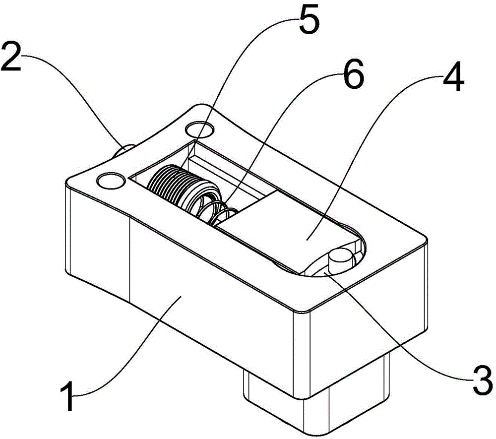
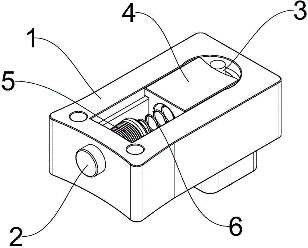
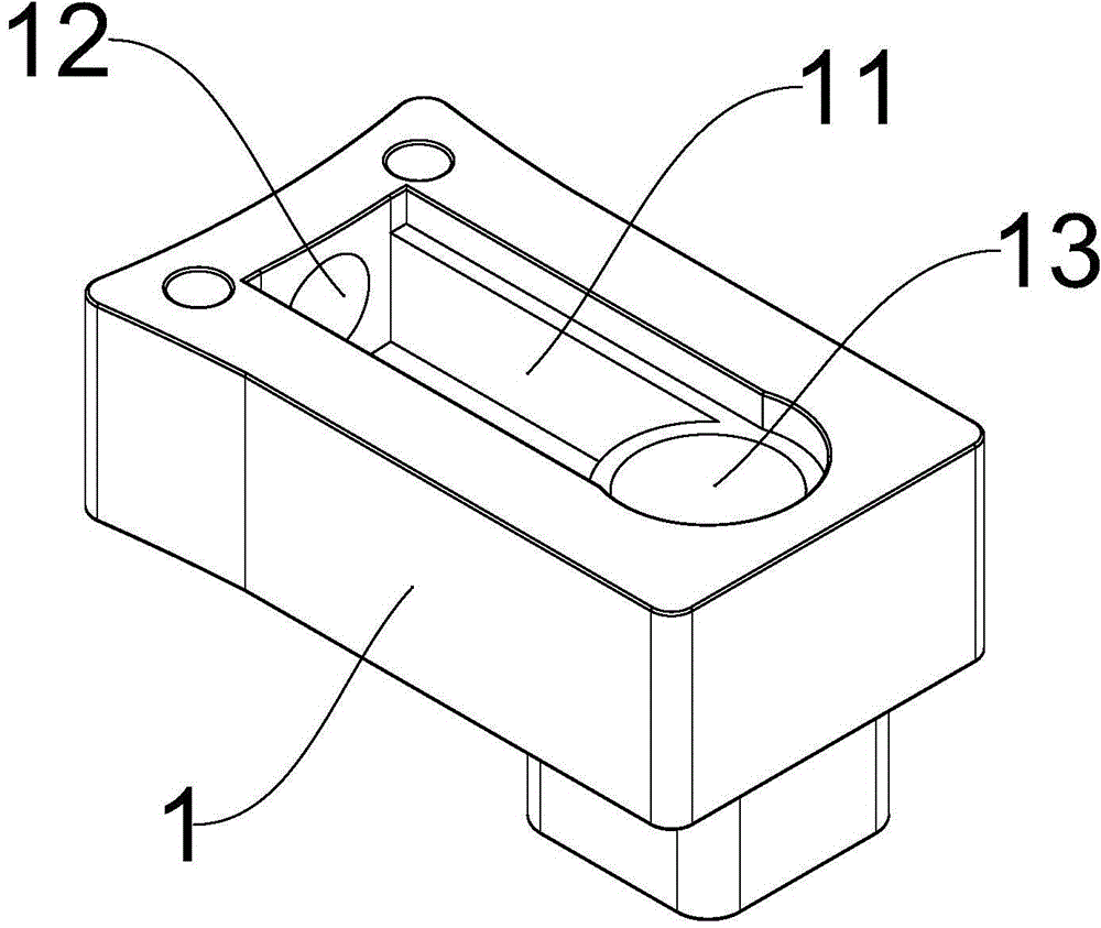
[0025] like figure 1 , figure 2 As shown, a lock with an anti-self-locking structure includes a lock case 1, a dead bolt 2, a lock cylinder 3 and a push block 4, as image 3 , Figur...


PUM


Abstract

The invention discloses a lock with a self-locking preventing structure. The lock comprises a lock shell, a lock bolt, a lock cylinder and a push block. The lock shell is provided with a mounting cavity. One end of the mounting cavity is provided with a bolt mounting hole, and the other end of the mounting cavity is provided with a cylinder mounting hole. The bolt mounting hole is arranged perpendicularly to the cylinder mounting hole. The lock bolt and the push block are disposed in the mounting cavity. One end of the lock bolt passes through the bolt mounting hole. The tail end of the lock bolt is connected with the head part of the push block. The tail end of the push block is provided with an arc-shaped end face. The invention has the advantages that the lock has a return spring capable of preventing the lock bolt from being automatically ejected and thus has the self-locking preventing structure; in addition, a push spring is adopted to drive the lock bolt to move forward so as to effectively prevent rigid drive of the lock bolt via a key, the key is not easy to break and therefore long service lifetime is achieved.

Description

technical field [0001] The invention relates to a lock, more precisely a lock with an anti-self-locking structure. Background technique [0002] Chinese utility model patent 200920113021.9 discloses a lock device for electric vehicle brake assembly, which includes a linkage gate, a waist-shaped hole is arranged on the joint gate, and a rotating block is arranged on the lock head. The block is installed in the waist-shaped hole, and the linkage gate is driven by the rotating block and the waist-shaped hole, and the lock cylinder is further driven forward and backward to realize the function of a lock, but the lock cylinder must be used to move forward and backward. Driven by a key, it is inconvenient to use, and the lock cylinder is easily ejected by vibration, so it is extremely unsafe to use this lock on electric power. Contents of the invention [0003] The present invention mainly solves the technical problems existing in the prior art, thereby providing a lock tongue ...

Claims


Application Information

Patent Timeline
Patent Type & Authority Applications(China)
IPC IPC(8): E05B15/00
Inventor 姜锦梅
Owner 姜锦梅
Learn More