
Image defogging method and equipment thereof

An image and equipment technology, applied in the field of image dehazing, can solve problems such as inaccurate image dehazing, and achieve the effect of solving inaccurate dehazing and improving image dehazing effect.

Active Publication Date: 2016-10-19
HANGZHOU HIKVISION DIGITAL TECH
View PDF3 Cites 12 Cited by
  • Summary
  • Abstract
  • Description
  • Claims
  • Application Information

AI Technical Summary

Problems solved by technology

[0005] Embodiments of the present invention provide a method and device for image defogging to solve the above-mentioned problem of inaccurate image defogging

Method used


Image

  • Image defogging method and equipment thereof
  • Image defogging method and equipment thereof
  • Image defogging method and equipment thereof

Examples


Embodiment Construction

[0039] In order to enable those skilled in the art to better understand the solutions of the present invention, the following will clearly and completely describe the technical solutions in the embodiments of the present invention in conjunction with the drawings in the embodiments of the present invention. Obviously, the described embodiments are only It is an embodiment of a part of the present invention, but not all embodiments. Based on the embodiments of the present invention, all other embodiments obtained by persons of ordinary skill in the art without making creative efforts shall fall within the protection scope of the present invention.

[0040] It should be noted that the terms "first" and "second" in the description and claims of the present invention and the above drawings are used to distinguish similar objects, but not necessarily used to describe a specific sequence or sequence. It is to be understood that the data so used are interchangeable under appropriate ...


PUM


Abstract

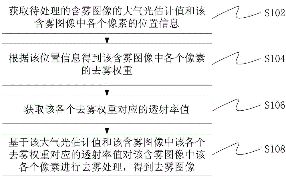
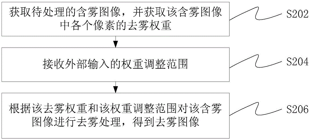
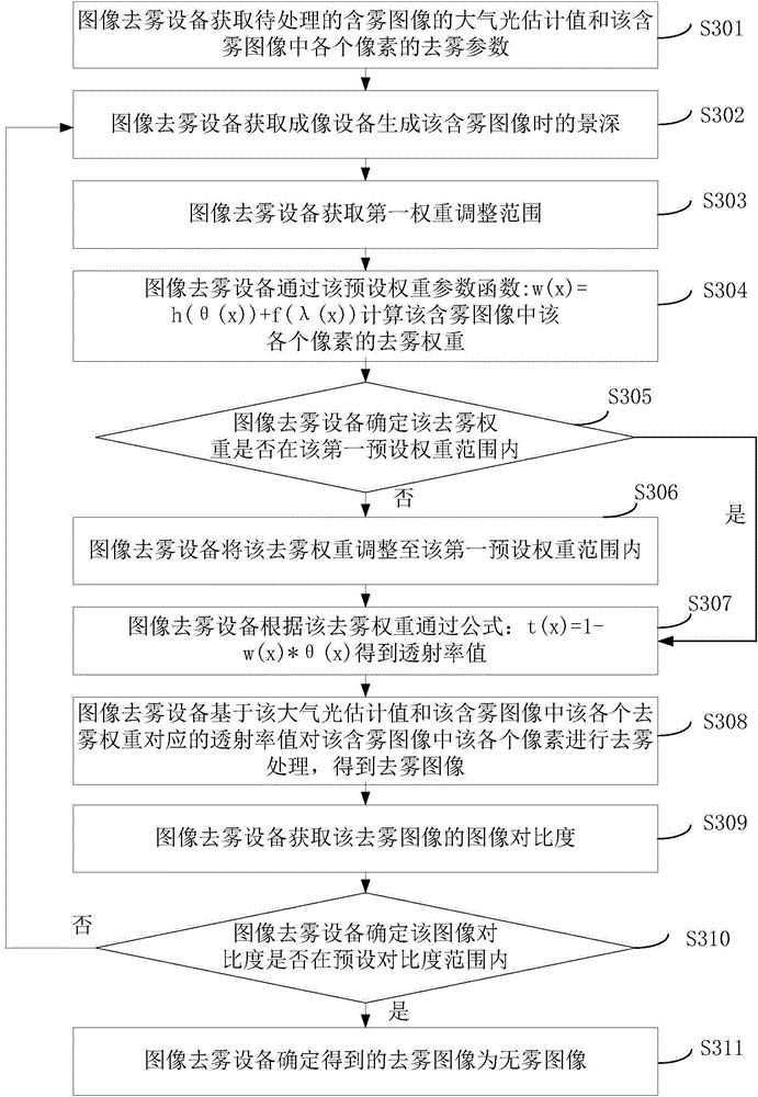
The invention discloses an image defogging method and equipment thereof. The method comprises the following steps of acquiring an atmospheric optical estimation value of a foggy image to be processed and position information of each pixel in the foggy image; according to the position information, acquiring a defogging weight of each pixel in the foggy image; acquiring a transmissivity value corresponding to each defogging weight; and based on the atmospheric optical estimation value and the transmissivity value corresponding to each defogging weight in the foggy image, carrying out defogging processing on each pixel in the foggy image so as to acquire a defogging image. By using the method and the equipment of the invention, local adjusting to an image defogging effect is realized and an integral image defogging effect is increased so that a problem that image defogging is not accurate is solved.

Description

technical field [0001] The present invention relates to the field of image processing, in particular to an image defogging method and device. Background technique [0002] When an imaging device (such as a video camera or camera) acquires images, due to the large number of particles such as water droplets in the atmosphere, as the distance between the object and the imaging device increases, the impact of the scattering of atmospheric particles on imaging gradually increases. It is mainly caused by two scattering processes: 1. When the reflected light on the surface of the object reaches the imaging device, it is attenuated due to the scattering of atmospheric particles; 2. The natural light enters the imaging device to participate in imaging due to the scattering of atmospheric particles. Their common The effect causes the contrast and saturation of the collected image to be low and the hue shifts, which not only affects the visual effect of the image, but also affects the ...

Claims


Application Information

Patent Timeline
Patent Type & Authority Applications(China)
IPC IPC(8): G06T5/00
Inventor 陈碧泉邓志辉宋其毅
Owner HANGZHOU HIKVISION DIGITAL TECH
Learn More