Locating support for cutting machine

A technology for positioning brackets and cutting machines, applied in the field of brackets, can solve the problems of unsatisfactory cutting effect, not due to the same plane, poor stability, etc., to achieve the effect of convenient and flexible cutting direction, prevention of violent shaking, and guaranteed cutting quality.

Inactive Publication Date: 2016-10-26
NANJING SHENGJIE MOTOR MFG
View PDF0 Cites 0 Cited by
  • Summary
  • Abstract
  • Description
  • Claims
  • Application Information

AI Technical Summary

Problems solved by technology

[0002] The existing manual cutting machine mainly relies on manually lifting the cutting machine to move downwards to cut. Although this cutting method is relatively flexible, the operator can control the cutting position and cutting direction at will, but the problem is that the stability is very poor. , because the cutting machine shakes violently during the cutting process, and manpower cannot control the shaking of the cutting machine, it is basically impossible to complete the straight line cutting in the actual cutting process, resulting in the cutting surface of the final cut item not being on the same plane, and the cutting effect is not Very ideal, unable to meet the process and technical requirements

Method used


Image

  • Locating support for cutting machine
  • Locating support for cutting machine

Examples


Embodiment 1

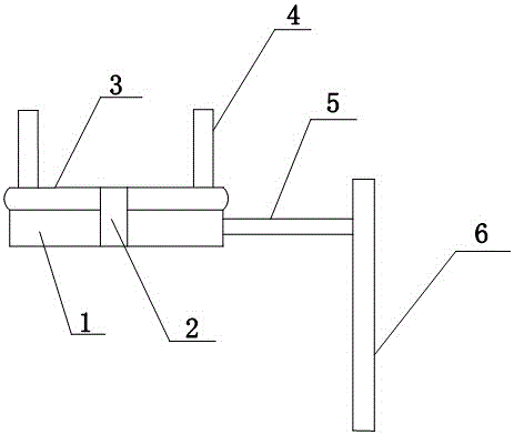
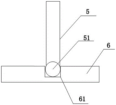
[0013] Such as figure 1 and figure 2 As shown, the present invention provides a cutting machine positioning bracket, including a support platform 1, the center of the support platform 1 is provided with an upwardly extending rotating shaft 2, and a rotating platform 3 is provided above the support platform 1. The rotating platform 3 and the rotating shaft 2 are integrally formed. The rotating platform 3 is provided with two positioning plates 4 perpendicular to the rotating platform 3 for fixing the cutting machine. The two positioning plates 4 are relative to the longitudinal axis of the rotating shaft 2. Symmetrically arranged, one side of the support platform 1 is provided with a horizontal connecting rod 5, one end of the connecting rod 5 is fixed on the support platform 1, and the other end is snapped into the longitudinal groove 61 of the vertical frame 6, the The connecting rod 5 can move up and down in the longitudinal groove 61, the connecting end of the connecting ...

Embodiment 2

[0015] First place the cutting machine between the two positioning plates 4 on the rotating platform 3, then turn the rotating platform 3 to adjust the cutting position of the cutting machine, start the gas cutting machine, the operator controls the cutting machine to cut and press down, the rotating platform 3 is on Driven by the connecting rod 5, it gently moves downwards. Since the connecting rod 5 moves vertically in a straight line in the longitudinal groove 61, the cutting track of the cutting machine is on the same straight line, realizing linear cutting.


PUM


Abstract

The invention discloses a cutting machine positioning bracket, which includes a support platform, an upwardly extending rotating shaft is arranged at the center of the supporting platform, a rotating platform is arranged on the supporting platform, and the rotating platform and the rotating shaft are integrally formed The rotating platform is provided with two positioning plates perpendicular to the rotating platform for fixing the cutting machine, the two positioning plates are arranged symmetrically with respect to the longitudinal axis of the rotating shaft, and one side of the supporting platform is provided with a transverse A connecting rod, one end of the connecting rod is fixed on the support platform, and the other end is fitted in the longitudinal groove of the vertical frame, and the connecting rod can move up and down in the longitudinal groove. The invention can make the cutting track of the cutting machine always be on the same straight line under the action of the connecting rod, thereby realizing straight line cutting, so the cutting effect of the cutting machine under the action of the bracket is greatly improved, and finally the cutting quality of the product is effectively improved. Assure.

Description

technical field [0001] The invention relates to a bracket, in particular to a cutting machine positioning bracket. Background technique [0002] The existing manual cutting machine mainly relies on manually lifting the cutting machine to move downwards to cut. Although this cutting method is relatively flexible, the operator can control the cutting position and cutting direction at will, but the problem is that the stability is very poor. , because the cutting machine shakes violently during the cutting process, and manpower cannot control the shaking of the cutting machine, it is basically impossible to complete the straight line cutting in the actual cutting process, resulting in the cutting surface of the final cut item not being on the same plane, and the cutting effect is not Very ideal, unable to meet the process and technical requirements. Contents of the invention [0003] Purpose of the invention: In order to overcome the deficiencies in the prior art, provide a ...

Claims


Application Information

Patent Timeline
Patent Type & Authority Applications(China)
IPC IPC(8): B23K7/10
CPCB23K7/10
Inventor 陶和生
Owner NANJING SHENGJIE MOTOR MFG
Why Eureka
Try Eureka