Optimization method for automobile hydraulic torque converter

A hydraulic torque converter and optimization method technology, applied in the direction of instruments, genetic rules, electrical digital data processing, etc., can solve the problems of high cost, heavy workload, and long research cycle, so as to reduce workload, The effect of optimizing comprehensive performance and reducing R&D and production costs

Inactive Publication Date: 2016-10-26
TONGJI UNIV +1
View PDF3 Cites 4 Cited by
  • Summary
  • Abstract
  • Description
  • Claims
  • Application Information

AI Technical Summary

Problems solved by technology

The research cycle is long, the workload is heavy, and the cost is high

Method used


Image

  • Optimization method for automobile hydraulic torque converter
  • Optimization method for automobile hydraulic torque converter
  • Optimization method for automobile hydraulic torque converter

Examples


Embodiment Construction

[0028] The embodiments of the present invention will be described in detail below with reference to the accompanying drawings, but the present invention can be implemented in many different ways defined and covered by the claims.

[0029] Embodiments of the present invention will be described in detail below in conjunction with the accompanying drawings.

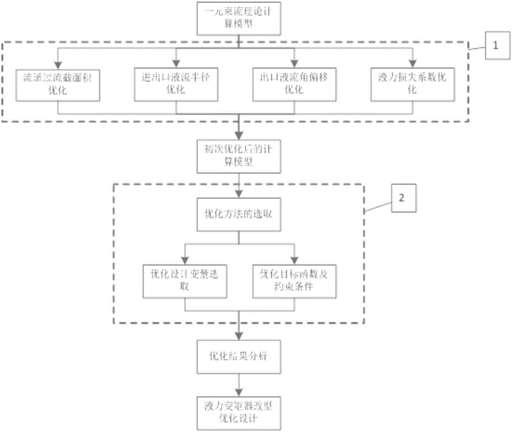
[0030] The invention uses the theoretical calculation model of the unitary beam current of the hydraulic torque converter as the basic model to optimize the design. The calculation model of the unitary beam flow theory makes the following assumptions on the internal flow characteristics of the torque converter: 1) The liquid flow is equivalently concentrated in a streamline determined by the blade surface; 2) The flow at the outlet of the impeller is not affected by The influence of the flow state at the inlet; 3) The liquid flow state at the inlet of the latter working wheel is completely consistent with the flow state at t...


PUM


Abstract

The invention discloses an optimization method for an automobile hydraulic torque converter. Primary optimization and secondary optimization are carried out based on a unitary beam theory calculation model. The method has the advantages that the primary optimization is modifying parameters in the unitary beam theory calculation model, thereby improving calculation precision of the calculation model; and the secondary optimization is optimizing comprehensive performance of the hydraulic torque converter.

Description

technical field [0001] The invention relates to an optimization method of an automobile hydraulic torque converter. Background technique [0002] The early development of the hydraulic torque converter is based on experience, using a variety of models and tests to screen, improve, and finally finalize the shape. With the development of technology and the establishment of theory, it is required to apply calculation methods to design, and to make the test performance of the product consistent with the calculation performance. At present, the calculation model of unitary beam flow theory is widely used. For the internal flow characteristics of the torque converter, assumptions are made such as that the liquid flow is equivalently concentrated in a streamline determined by the curved surface of the blade. However, the flow field in the torque converter is a complex three-dimensional flow. There is a large area of ​​backflow and jet flow at the outlet of each impeller, and there...

Claims


Application Information

Patent Timeline
Patent Type & Authority Applications(China)
IPC IPC(8): G06F17/50G06N3/12
CPCG06F30/15G06F30/367G06N3/126Y02T10/40
Inventor 吴光强陈洁陈达观张博文陈祥邹玉国张春祖王立军
Owner TONGJI UNIV
Why Eureka
Try Eureka