Eureka AIR delivers breakthrough ideas for toughest innovation challenges, trusted by R&D personnel around the world.

A kind of efuse circuit and programmable storage device

A storage device and circuit technology, which is applied in the field of programming control, can solve the problems of multi-metal layer fuse blown and reliability difficult to control, etc.

Active Publication Date: 2019-11-26
ANYKA (GUANGZHOU) MICROELECTRONICS TECH CO LTD
View PDF5 Cites 0 Cited by
  • Summary
  • Abstract
  • Description
  • Claims
  • Application Information

AI Technical Summary

Problems solved by technology

[0005] The purpose of the embodiments of the present invention is to provide an EFUSE circuit and a programmable storage device, aiming to solve the problem that the traditional EFUSE technology adopts the method of fusing a multi-metal layer fuse, and its reliability is difficult to control

Method used


Image

  • A kind of efuse circuit and programmable storage device
  • A kind of efuse circuit and programmable storage device
  • A kind of efuse circuit and programmable storage device

Examples


Embodiment 1

[0037] A first embodiment of the present invention provides an EFUSE circuit.

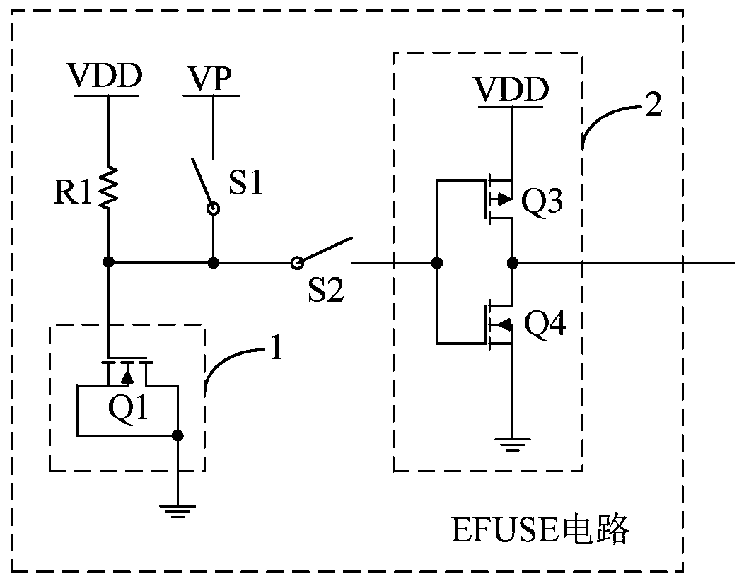
[0038] figure 1 A circuit structure diagram of the EFUSE circuit provided by the first embodiment of the present invention is shown, and for convenience of description, only parts related to the embodiment of the present invention are shown.

[0039] An EFUSE circuit, the EFUSE circuit comprising: a voltage dividing resistor R1, a gate oxide breakdown tube 1, a switch S1, a switch S2 and a NOT gate circuit 2;

[0040] The voltage dividing resistor R1 and the gate oxide breakdown tube 1 are connected in series between the first power supply VDD and the ground, the common end of the voltage dividing resistor R1 and the gate oxide breakdown tube 1 is connected to the NOT gate circuit 2 through the switch S2, and the gate oxide breakdown The control terminal of tube 1 is connected to the second power supply VP through switch S1;

[0041]When not programmed, the switch S1 is controlled to be turned of...

no. 2 example

[0055] The second embodiment of the present invention provides a programmable storage device.

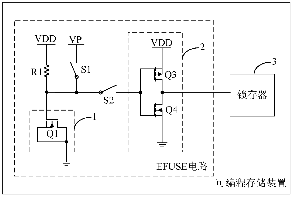
[0056] image 3 A circuit structure diagram of the programmable storage device provided by the second embodiment of the present invention is shown, and for convenience of description, only parts related to the embodiment of the present invention are shown.

[0057] A programmable storage device, the programmable storage device includes an EFUSE circuit, and the EFUSE circuit includes: a voltage dividing resistor R1, a gate oxide breakdown tube 1, a switch S1, a switch S2, and a NOT gate circuit 2;

[0058] The voltage dividing resistor R1 and the gate oxide breakdown tube 1 are connected in series between the first power supply VDD and the ground, the common end of the voltage dividing resistor R1 and the gate oxide breakdown tube 1 is connected to the NOT gate circuit 2 through the switch S2, and the gate oxide breakdown The control terminal of tube 1 is connected to the second po...


PUM


Abstract

The invention belongs to the field of programming controlling and provides an EFUSE (electrically programmable fuse) circuit and a programmable storing device. The EFUSE circuit comprises a divider resistor R1, a gate-oxide breakdown pipe and a switch S1. The divider resistor R1 and the gate-oxide breakdown pipe are connected between a first power source and the ground in series. The control end of the gate-oxide breakdown pipe is connected with a second power source through the switch S1. When programming is not carried out, the gate-oxide breakdown pipe is equivalent to a capacitor and divides a voltage with the divider resistor R1, and the divider resistor R1 and the common end of gate-oxide breakdown pipe output high level; when programming is carried out, the second power source outputs a high voltage to break down the gate-oxide breakdown pipe, the broken gate-oxide breakdown pipe is equivalent to a resistor, and the divider resistor R1 and the common end of the gate-oxide breakdown pipe output low level. The change of output logic 0 and output logic 1 is achieved through the capacitance / voltage characteristic change of the gate-oxide breakdown pipe before and after breakdown, then, programming control is achieved, and the reliability of programming is enhanced.

Description

technical field [0001] The invention belongs to the field of programming control, in particular to an EFUSE circuit and a programmable storage device. Background technique [0002] EFUSE (Electrically programmable Fuse, electrically programmable fuse) technology is a one-time programming storage technology widely used in chips, which can be used to record the configuration information of the chip, or to repair the integrated circuit due to the semiconductor process. Unavoidable bad components. When the chip fails, the EFUSE circuit in the chip can repair the defect of the chip. When the chip runs incorrectly, the EFUSE circuit can automatically correct the chip. The EFUSE circuit writes logic 0 or logic 1 through the corresponding circuit and signal control. It is used to replace the corresponding failure part of the chip to complete the operation of input logic 0 or logic 1. [0003] Most of the existing EFUSE technologies are based on the multi-metal layer fuse fusing me...

Claims


Application Information

Patent Timeline
Patent Type & Authority Patents(China)
IPC IPC(8): G11C17/18G11C17/16
CPCG11C17/16G11C17/18
Inventor 潘少辉胡胜发
Owner ANYKA (GUANGZHOU) MICROELECTRONICS TECH CO LTD
Why Eureka
Eureka Blog
Learn More