Charger capable of automatically distributing charging current

A charging current, automatic distribution technology, applied in the direction of charging/discharging current/voltage regulation, current collectors, battery circuit devices, etc. problem, to achieve the effect of increasing the charging power and improving the charging efficiency

Active Publication Date: 2016-10-26
李文杰
View PDF4 Cites 8 Cited by
  • Summary
  • Abstract
  • Description
  • Claims
  • Application Information

AI Technical Summary

Problems solved by technology

[0003] Existing chargers usually charge an electronic device in a charging slot with a constant output power, that is, whether it is a large-capacity electronic device or a small-capacity electronic device, the output power of the existing charger is always It is the same, this will increase the charging time of large-capacity electronic devices, and use a larger output power, it is easy to heat up small-capacity electronic devices, and then affect the performance of small-capacity electronic devices
[0004] In addition, when the existing charger leaves the factory, the charging power of each charging slot is allocated. For the charging slot that has been fully charged or stopped charging or has no electronic equipment placed, the existing charger does not allocate the power occupied by the charging slot to the charging slot. Other slots lead to low overall charging efficiency of existing chargers

Method used


Image

  • Charger capable of automatically distributing charging current
  • Charger capable of automatically distributing charging current
  • Charger capable of automatically distributing charging current

Examples


Embodiment Construction

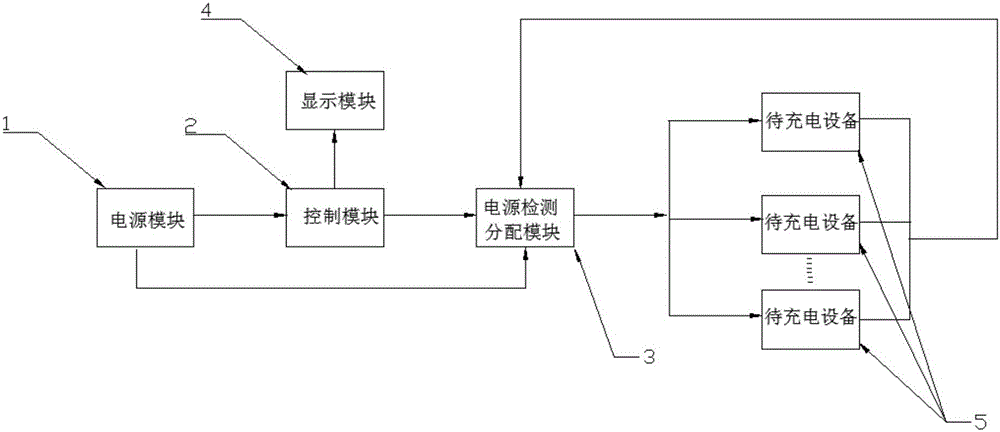
[0024] see figure 1 , which is a schematic diagram of an embodiment of a charger capable of automatically distributing charging current in the present invention. The charger capable of automatically distributing charging current includes a power supply module 1, a control module 2, a detection distribution module 3, a display module 4 and a key module.

[0025] The power supply module 1 supplies power to the control module 2, the detection distribution module 3, the display module 4 and the button module.

[0026] The detection distribution module 3 is connected with the control module 2 and multiple external devices 5 to be charged, and detects the voltage characteristic of each device 5 to be charged, and forwards the voltage characteristic signal to the control module 2 . The detection distribution module also detects the charging state of each device to be charged 5, and forwards the charging state signal to the control module 2, and sends the charging current distributio...


PUM


Abstract

The invention discloses a charger capable of automatically distributing charging current. The charger comprises a power supply module, a control module and a distribution detecting module. The distribution detecting module is connected with the control module and a plurality of sets of to-be-charged equipment. Furthermore the distribution detecting module detects the voltage characteristic of each set of to-be-charged equipment and transmits a voltage characteristic signal to the control module. The distribution detecting module further detects the charging state of each set of to-be-discharged equipment and furthermore forwards a charging state signal to the control module. Furthermore the distribution detecting module forwards the charging current distribution instruction of the control module to each set of to-be-discharged equipment in real time. The control module outputs a specific charging total power and furthermore transmits a charging current distribution instruction to each set of to-be-discharged equipment according to the charging state signal of each set of to-be-discharged equipment. The charger realizes large-power discharging on large-capacity to-be-discharged equipment and low-power charging on low-capacity to-be-discharged equipment. When charging to one set of to-be-discharged equipment is stopped, the charging current to the to-be-discharged equipment is automatically distributed to other to-be-discharged equipment, thereby improving charging efficiency.

Description

technical field [0001] The invention relates to the charging field, in particular to a charger capable of automatically distributing charging current. Background technique [0002] With the development of science and technology, human beings are increasingly dependent on electronic equipment. As a device that can conveniently and quickly charge electronic equipment, people have higher and higher requirements for chargers. [0003] Existing chargers usually charge an electronic device in a charging slot with a constant output power, that is, whether it is a large-capacity electronic device or a small-capacity electronic device, the output power of the existing charger is always It is the same, this will increase the charging time of large-capacity electronic devices, and use a larger output power, which will easily heat up small-capacity electronic devices, which will affect the performance of small-capacity electronic devices. [0004] In addition, when the existing charger...

Claims


Application Information

Patent Timeline
Patent Type & Authority Applications(China)
IPC IPC(8): H02J7/00
CPCH02J7/007H02J7/0085Y02E60/10
Inventor 李文杰
Owner 李文杰
Why Eureka
Try Eureka