Passive wireless current sensor based on dual-winding current transformer

A current transformer and current sensor technology, applied in voltage/current isolation, measurement using digital measurement technology, etc., can solve the problem of inability to maximize energy efficiency, inability to achieve maximum power tracking, and unfavorable miniaturization of monitoring equipment, etc. problems, to achieve the effect of improving energy harvesting efficiency, accurate proportional relationship control, and reducing power consumption

Pending Publication Date: 2019-01-25
石家庄杰泰特动力能源有限公司 +1
View PDF8 Cites 9 Cited by
  • Summary
  • Abstract
  • Description
  • Claims
  • Application Information

AI Technical Summary

Problems solved by technology

This passive wireless current sensor product based on current transformers has the following problems: 1. Using two transformers to collect current signals and energy respectively increases the volume of the transformer, which is not conducive to the miniaturization of monitoring equipment ;2. As the voltage of the charging capacitor / battery changes, there will be a maximum power point in the output power of the current transformer, and this power point will change with the current on one side. This product cannot achieve maximum power tracking. In this way, the maximum energy harvesting efficiency cannot be achieved

Method used


Image

  • Passive wireless current sensor based on dual-winding current transformer
  • Passive wireless current sensor based on dual-winding current transformer
  • Passive wireless current sensor based on dual-winding current transformer

Examples


Embodiment Construction

[0019] The technical solution in this embodiment will be clearly and completely described below in conjunction with the accompanying drawings, and the embodiment is only a part of the embodiments of the present invention, but not all of the embodiments. All other embodiments obtained by persons of ordinary skill in the art without creative efforts fall within the protection scope of the present invention.

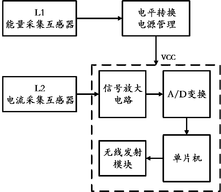
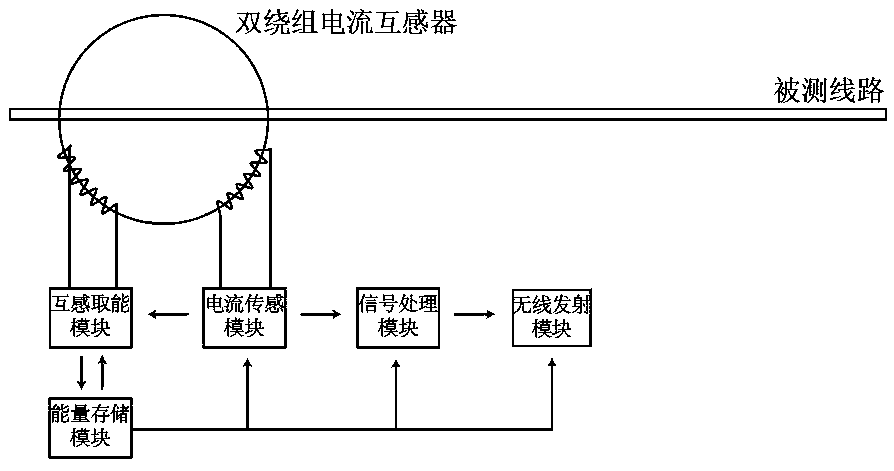
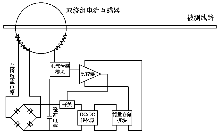
[0020] Please refer to figure 2 As shown, the present invention provides a passive wireless current sensor based on a double-winding current transformer, including a double-winding current transformer, a mutual inductance energy harvesting module, an energy storage module, a current sensing module, a signal processing module, and a wireless transmission module , the double-winding current transformer includes a primary side winding connected to the line under test and two secondary side windings, and the two secondary side windings are respectively connected to the mutual ...


PUM


Abstract

The invention discloses a passive wireless current sensor based on a dual-winding current transformer. The passive wireless current sensor comprises the dual-winding current transformer, a mutual inductance energy extraction module, an energy storage module, a current sensing module, a signal processing module and a wireless transmitting module, wherein the dual-winding current transformer comprises a primary side winding connected with a tested circuit, and two secondary side windings; and the two secondary side windings are connected with the mutual inductance energy extraction module and the current sensing module respectively. The passive wireless current sensor can be applied to an intelligent power grid electric energy monitoring system, does not need an external power supply systemto provide energy, only uses one transformer for energy collection and current sensing, reduces the size of the system and facilitates installation. The passive wireless current sensor can perform maximum power tracking according to the magnitude of a current measured by means of the current sensing module, greatly improves the power output of the energy extraction module, and reduces the startingcurrent of the system, thereby improving the reliability of the sensor and expanding the use range.

Description

technical field [0001] The invention relates to the technical field of power facilities, in particular to a passive wireless current sensor based on a double-winding current transformer. Background technique [0002] In the power monitoring and management system, due to the measurement failure of the meter itself, the illegal modification and detour of the meter by the user end, the aging line loss of the power supply equipment, etc., the line loss will occur. At present, the means of identifying the cause of the line loss mainly rely on manual on-site investigation and analysis. , low work efficiency and high labor costs. The smart grid implements online real-time monitoring of the transmission circuit, which has high monitoring efficiency, saves time and effort, and is of great significance to the safety and stability of the power system. In the prior art, the current sensors on the smart grid mostly use passive wireless current sensor products based on current transforme...

Claims


Application Information

Patent Timeline
Patent Type & Authority Applications(China)
IPC IPC(8): G01R19/25G01R15/18
CPCG01R15/18G01R19/25
Inventor 董玮戚南剑孙文钰
Owner 石家庄杰泰特动力能源有限公司
Why Eureka
Try Eureka