High-intensity pulse current crack arrest discharge apparatus

A pulse current and discharge device technology, applied in battery circuit devices, circuit devices, collectors, etc., can solve the problem of inability to have equipotential secondary rapid input, capacitor switching switch secondary input speed is slow, and discharge circuit consumes a lot of energy and other issues, to achieve the effect of intelligence and selectivity, little impact on the surrounding environment, and low charging power

Inactive Publication Date: 2016-03-23
SHENYANG JIANZHU UNIVERSITY
View PDF2 Cites 8 Cited by
  • Summary
  • Abstract
  • Description
  • Claims
  • Application Information

AI Technical Summary

Problems solved by technology

[0002] At present, in the high-voltage discharge device, the thyristor capacitor switching switch is widely used to control the capacitor switching, but because the phase difference of the three-phase electricity is 120 degrees, and the thyristor itself has the characteristics of current zero-crossing breaking, when the switch is breaking Afterwards, the residual voltage of one phase capacitor will be much higher than the peak value of the line voltage, and the conditions for the second rapid input of the equipotential cannot be met in a short period of time; when the voltage fluctuates greatly, even if the capacitor switching Capacitor breaking, because the thyristor itself has the characteristics of zero current breaking, the residual voltage of the load capacitor at this time is the peak value of the AC voltage when the thyristor is broken. It is impossible to have the condition of equipotential secondary rapid input. Therefore, in order to achieve the purpose of faster secondary input, the discharge resistor is connected to the output terminal of the capacitor switching switch or the capacitor input terminal. Generally, the RC time constant is large and the discharge speed is slow. , which will cause large energy consumption of the discharge circuit, poor discharge effect, slow secondary input speed of the capacitor switching switch, and low output power

Method used


Image

  • High-intensity pulse current crack arrest discharge apparatus
  • High-intensity pulse current crack arrest discharge apparatus
  • High-intensity pulse current crack arrest discharge apparatus

Examples


Embodiment Construction

[0019] The technical solution of the present invention will be described in detail below in conjunction with the accompanying drawings and specific embodiments, so as to further understand the present invention, but it is not intended to limit the protection scope of the appended claims of the present invention.

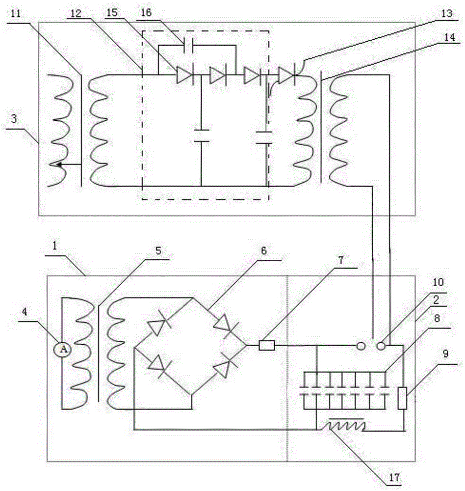
[0020] A high-intensity pulse current crack arresting discharge device includes a charging circuit unit 1 , a triggering circuit unit 3 , and a discharging circuit unit 2 .

[0021] The charging circuit unit 1 includes: a voltage regulator 4, a high-voltage transformer 5, a bridge rectifier 6, and a charging current limiting resistor 7; the voltage regulator 4 is connected to the high-voltage transformer 5, and a bridge type Rectifier 6, one end of the bridge rectifier 6 is connected to the charging current-limiting resistor 7, and the other end is directly connected to the pulse capacitor bank 8 in the discharge circuit unit 2 through a wire; the charging process is:...


PUM


Abstract

The invention discloses a high-intensity pulse current crack arrest discharge apparatus. The apparatus comprises a charge loop unit, a trigger loop unit and a discharge loop unit. The trigger loop unit is introduced; a relatively high-intensity pulse current is generated by utilizing a principle that a high-voltage pulse capacitor bank generates an instant strong pulse current during energy storage and discharge; and at the moment that the pulse current passes through a metal plate with a crack, joule heat can be generated at a crack tip under a bypass current concentration effect, and the local temperature of the crack tip is increased and even exceeds a melting point of a material, so that the crack tip is molten to form a molten hole, the curvature radius of the crack tip is increased, the stress concentration is eliminated, and crack emerging and spreading of the crack tip can be inhibited. The apparatus is low in charge power, high in instant output electric energy and mature in technical principle, has intelligence and selectiveness for crack repair, and is simple to operate and small in influence on surrounding environment.

Description

technical field [0001] The invention belongs to a capacitor pulse discharge device, in particular to a high-intensity pulse current crack arrest discharge device. Background technique [0002] At present, in the high-voltage discharge device, the thyristor capacitor switching switch is widely used to control the capacitor switching, but because the phase difference of the three-phase electricity is 120 degrees, and the thyristor itself has the characteristics of current zero-crossing breaking, when the switch is breaking Afterwards, the residual voltage of one phase capacitor will be much higher than the peak value of the line voltage, and the conditions for the second rapid input of the equipotential cannot be met in a short period of time; when the voltage fluctuates greatly, even if the capacitor switching Capacitor breaking, because the thyristor itself has the characteristics of zero current breaking, the residual voltage of the load capacitor at this time is the peak v...

Claims


Application Information

Patent Timeline
Patent Type & Authority Applications(China)
IPC IPC(8): H02J7/00
CPCH02J7/0063H02J7/345
Inventor 马振宁汪青杰王逊孙小巍翟中海
Owner SHENYANG JIANZHU UNIVERSITY
Why Eureka
Try Eureka