
A self-starting vernier permanent magnet motor with variable poles

A permanent magnet motor and vernier technology, applied in the direction of synchronous machines, electromechanical devices, electrical components, etc., can solve the problems of low starting torque, decreased output torque and efficiency, and lack of self-starting ability, so as to reduce the equivalent gas gap effect

Active Publication Date: 2019-01-11
HUAZHONG UNIV OF SCI & TECH
View PDF3 Cites 0 Cited by
  • Summary
  • Abstract
  • Description
  • Claims
  • Application Information

AI Technical Summary

Problems solved by technology

[0010] However, the above-mentioned technical solutions cannot be directly applied to the vernier motors for the following reasons: (1) In order to increase the output torque, the existing vernier motors all adopt the structure of surface-mounted magnetic steel, and this structure causes even if the starting unit is added, the starting Torque is also quite low, almost does not have self-starting ability; (2) the squirrel cage winding that adopts in the prior art can not be applied in vernier motor, and it can produce very large induction current when motor steady-state operation, produces extremely Large braking torque, so the output torque and efficiency will drop sharply, completely losing the advantages of the vernier motor; (3) If the pole-changing starting scheme in the prior art is used, it will bring the same problems as using squirrel cage windings , the starting performance of the motor is still not strong enough, and the situation of "big horse and small cart" is prone to occur when using it

Method used


Image

  • A self-starting vernier permanent magnet motor with variable poles
  • A self-starting vernier permanent magnet motor with variable poles
  • A self-starting vernier permanent magnet motor with variable poles

Examples


Embodiment Construction

[0033] In order to make the object, technical solution and advantages of the present invention clearer, the present invention will be further described in detail below in conjunction with the accompanying drawings and embodiments. It should be understood that the specific embodiments described here are only used to explain the present invention, not to limit the present invention. In addition, the technical features involved in the various embodiments of the present invention described below can be combined with each other as long as they do not constitute a conflict with each other.

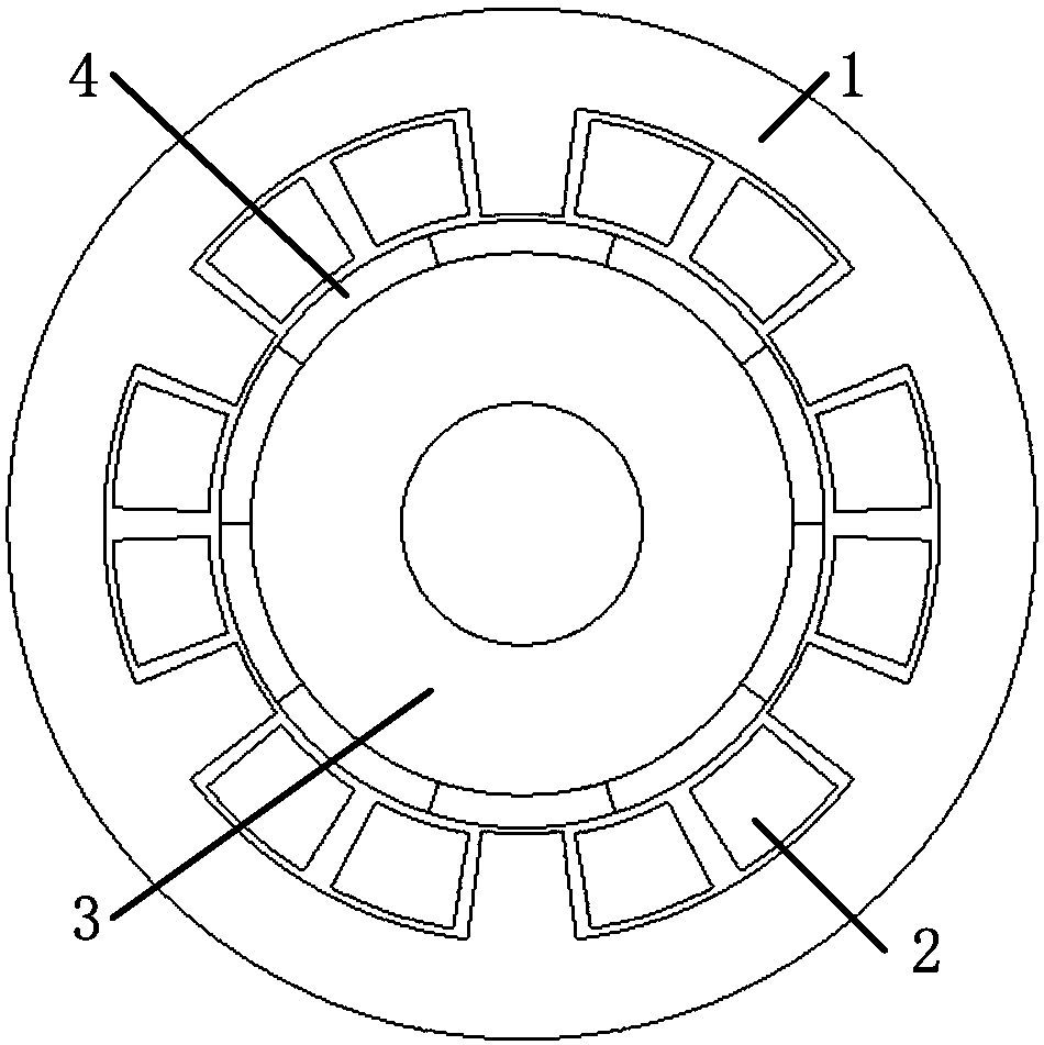
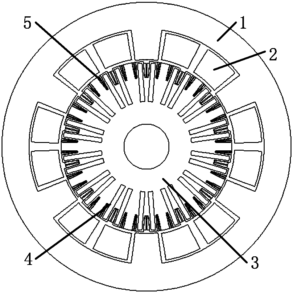
[0034] According to the self-starting vernier motor of one embodiment of the present invention, as figure 2 As shown, it includes a stator core 1, a rotor core 3 coaxially sleeved in the stator core, wherein the stator core 1 and the rotor core 3 are preferably annular, and the inner ring surface of the stator core 1 is provided with Open slots are used as stator slots, and semi-closed slots a...


PUM


Abstract

The invention discloses a pole variable self-starting vernier permanent magnet motor comprising a stator iron core, wherein open slots, as stator slots, are arranged on the inner ring surface of the stator iron core along the circumference; a rotor iron core, wherein closed slots, as rotor slots, are arranged on the outer surface of the rotor iron core, corresponding to the inner ring surface of the stator iron core, along the circumference; and multiple permanent magnets which are arranged in the rotor iron core. Each stator winding is a set of pole variable single winding with double poles. Each rotor winding is a short circuit three-phase wire wrapping type winding. The number of pole pairs when each stator winding is started is equal to the number of the pole pairs connected with each rotor winding, the number of the pole pairs when each stator winding is operated normally is equal to the result of subtracting the number of stator teeth by the number of the pole pairs of each permanent magnet, and the sum or difference between the number of the pole pairs when each stator winding is started and the number of the pole pairs when each stator winding is operated normally is not the integer multiple of the number of the stator teeth. According to the vernier permanent magnet motor, asynchronous self-starting of the motor can be realized, and the motor is pulled into synchronous operation when the motor approaches the synchronous speed. The motor is high in starting torque, high in output torque during stable operation and low in vibration noise during starting.

Description

technical field [0001] The invention belongs to the field of self-starting permanent magnet motors, and in particular relates to a vernier permanent magnet motor which uses a pole-changing method to realize self-starting. Background technique: [0002] Whether it is in industrial production, resource transmission or daily life, fans or water pumps are widely used. They use blades to push fluid and make it flow in a direction. These blades often use electric motors as the source of power. On the basis of 70% of China's electric motors consuming industrial electricity, the motors used for fans and water pumps account for more than 60% of all motors. It can be seen that the number of driving motors for domestic fans and water pumps is extremely large. Uses a lot of energy. [0003] The blades of fans and water pumps have three common characteristics. First, their operating speed is low and their output torque is relatively large. The motor is often connected to it through a ge...

Claims


Application Information

Patent Timeline
Patent Type & Authority Patents(China)
IPC IPC(8): H02K21/46H02K3/28
CPCH02K3/28H02K21/46
Inventor 曲荣海李大伟任翔
Owner HUAZHONG UNIV OF SCI & TECH
Features
  • Generate Ideas
  • Intellectual Property
  • Life Sciences
  • Materials
  • Tech Scout
  • Unparalleled Data Quality
  • Higher Quality Content
  • 60% Fewer Hallucinations
Learn More