CAN communication channel switching circuit for vehicles

A technology for CAN communication and switching circuits, which is applied in the field of vehicle CAN communication channel switching circuits, and can solve problems such as difficult to meet the requirements of vehicle CAN communication

Active Publication Date: 2016-11-02
SINO TRUK JINAN POWER
View PDF9 Cites 5 Cited by
  • Summary
  • Abstract
  • Description
  • Claims
  • Application Information

AI Technical Summary

Problems solved by technology

[0003] At present, some main controller chips in the domestic market are still widely used in product development. These products designed by the main controller with only one CAN channel can only simply realize the collection of vehicle driving information. In the existing It is already difficult to meet the CAN communication requirements of the vehicle

Method used


Image

  • CAN communication channel switching circuit for vehicles
  • CAN communication channel switching circuit for vehicles
  • CAN communication channel switching circuit for vehicles

Examples


Embodiment Construction

[0019] In order to facilitate those skilled in the art to better understand the present invention, the present invention will be described in further detail below in conjunction with the accompanying drawings and specific embodiments. The following is only exemplary and does not limit the protection scope of the present invention.

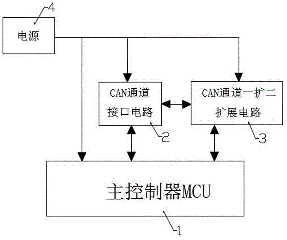
[0020] Such as figure 1 As shown, the vehicle CAN communication channel switching circuit of the present invention includes main controller MCU 1, CAN channel interface circuit 2, CAN channel one expansion two expansion circuit 3 and respectively to main controller MCU 1, CAN channel interface circuit 2, CAN channel A power supply 4 powered by channel one expansion two expansion circuit 3, the main controller MCU 1 is bidirectionally connected with the CAN channel interface circuit 2, and the CAN channel interface circuit 2 is bidirectionally connected with the CAN channel one expansion two expansion circuit 3; the main controller MCU 1 The 32-bit ...


PUM


Abstract

The invention discloses a CAN communication channel switching circuit for vehicles. The CAN communication channel switching circuit comprises a main controller MCU, a CAN channel interface circuit, a CAN channel one-to-two expanding circuit, and a power supply which supplies power for the main controller MCU, the CAN channel interface circuit and the CAN channel one-to-two expanding circuit respectively, wherein the main controller MCU is in bi-directional connection with the CAN channel interface circuit; and the CAN channel interface circuit is in bi-directional connection with the CAN channel one-to-two expanding circuit. Therefore, the problems that the main controller only has one CAN channel and is lack of CAN channel function are solved; vehicle information collection and diagnosis of two CAN channels of which the baud rates are 250 kpbs and 500 kpbs respectively are realized simultaneously by equipping different configurations on the CAN channels and using the CAN communication channel switching circuit.

Description

technical field [0001] The invention relates to a vehicle CAN communication channel switching circuit, which belongs to the technical field of vehicle CAN communication. Background technique [0002] Since the 1980s, major automobile manufacturers in the United States, Japan, and Europe have begun to equip their EFI vehicles with OBD. The initial OBD did not have a self-test function. OBD-II, which is more advanced than OBD, was produced in the mid-1990s. The American Society of Automotive Engineers (SAE) formulated a set of standard specifications, requiring all automobile manufacturers to provide a unified diagnostic mode in accordance with the OBD-II standard. In the 21st century At the beginning, China also issued a series of technical requirements for vehicle diagnosis OBD. [0003] At present, some main controller chips in the domestic market are still widely used in product development. These products designed by the main controller with only one CAN channel can only...

Claims


Application Information

Patent Timeline
Patent Type & Authority Applications(China)
IPC IPC(8): H04L29/10
CPCH04L69/32Y02P90/02
Inventor 李大帅刘子辉张文斌营健
Owner SINO TRUK JINAN POWER
Why Eureka
Try Eureka