Seat

a seat and seat technology, applied in the field of seats, can solve the problems of increasing the assembly steps required when the members are attached to the cushion frame, reducing the fatigue of the rider, and many assembly steps would be deemed disadvantageously burdensome, so as to reduce the fatigue of the rider, and reduce the effect of fatigu

Inactive Publication Date: 2020-02-06
TS TECH CO LTD
View PDF0 Cites 3 Cited by
  • Summary
  • Abstract
  • Description
  • Claims
  • Application Information

AI Technical Summary

Benefits of technology

[0009]With these in view, it is an object of the present invention to provide a seat which may be assembled in reduced number of assembly steps.
[0073]With this configuration, the second pad layers at the left and right sides of the hip point can be supported from below by the left and right second supporting members; accordingly, when a person is seated on the seat, the second pad layers can be restrained from sinking down. Consequently, the functionality of the second pad layers can be achieved sufficiently, so that the fatigue that would be felt can be reduced even on long periods of sitting. Moreover, since the first pad layer on and around the hip point can be supported from below by the first supporting member, the soft first pad layer can be restrained from sinking down excessively when a person is seated on the seat, so that an improved ride comfort can be achieved.

Problems solved by technology

The seat disclosed in Patent Document 1 requires assembly steps in which the S springs should be located in, laid on, and attached to the cushion frame, and moreover, the left and right inclining plates should be located at and secured by screws to the cushion frame; such many assembly steps would be deemed disadvantageously burdensome.
Furthermore, in the seat disclosed in Patent Document 1, the left and right inclining plates should be located at, and secured by the screws to the cushion frame independently of other members to be attached, which would disadvantageously increase the assembly steps required when the members are attached to the cushion frame.

Method used


Image

  • Seat
  • Seat
  • Seat

Examples


first embodiment

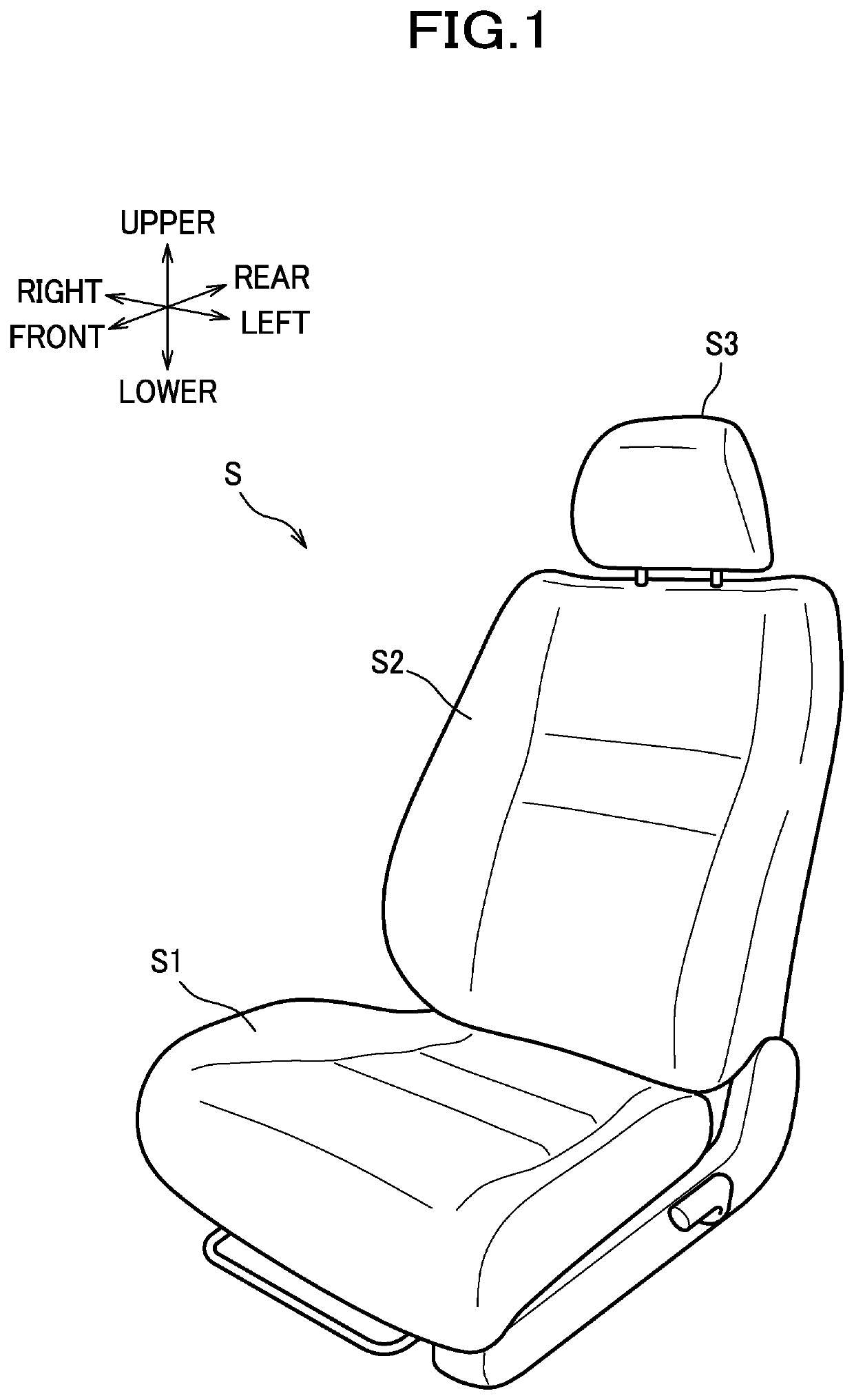
[0099]As shown in FIG. 1, a seat of the present embodiment is configured as a car seat S installed in an automobile, and includes a seat cushion S1, a seat back S2, and a headrest S3.

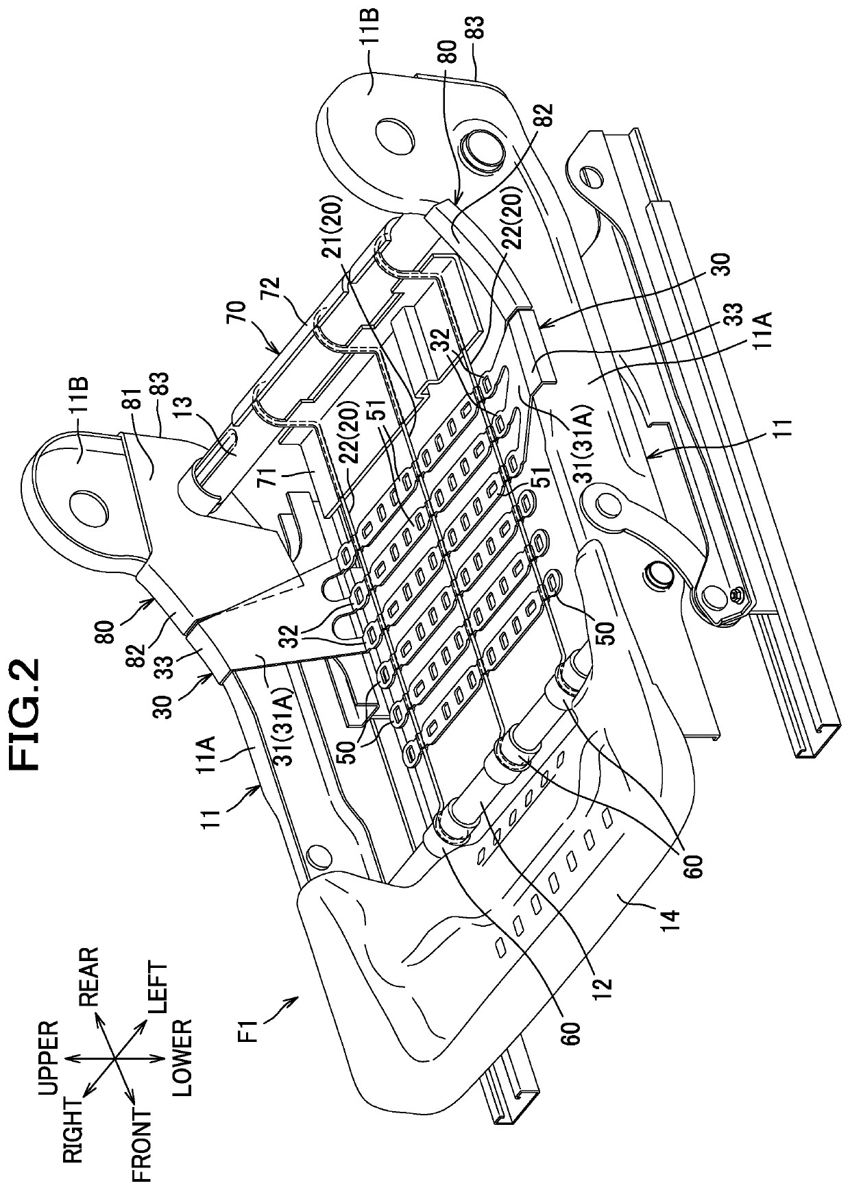
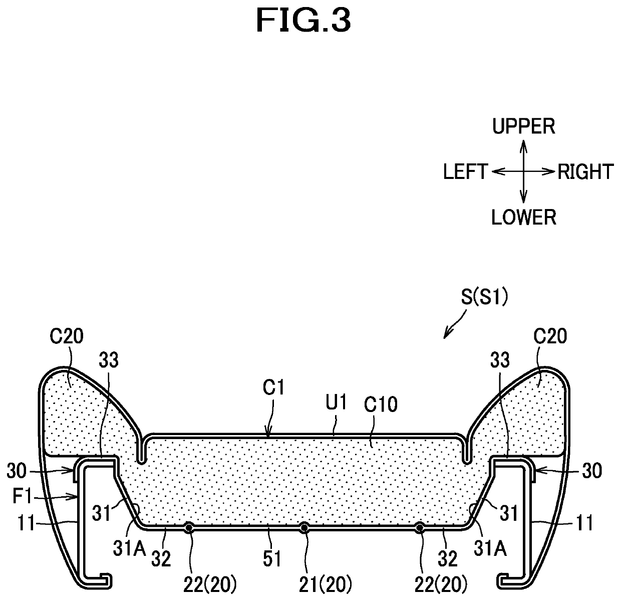
[0100]Inside the seat cushion S1, a cushion frame F1 as shown in FIG. 2 is incorporated. The cushion frame F1 is a member constituting a frame of the seat cushion S1. As shown in FIG. 3, the seat cushion S1 is constructed of the cushion frame F1 upholstered with a cushion pad C1 made of urethane foam or the like and an outer covering U1 made of fabrics, leather or the like.

[0101]As shown in FIG. 2, the cushion frame F1 includes left and right side frames 11, a front frame 12 and a rear frame 13 as front and rear cross members, and a pan frame 14.

[0102]The left and right side frames 11 are frames formed of sheet metal, and disposed separately from each other in a lateral direction. Each side frame 11 includes a side frame body 11A extending approximately in a front-rear direction, and a back attachment p...

second embodiment

[0143]Next, a description will be given of a second embodiment. In the following, the same components as those described above will be designated with the same reference characters, and a description thereof will be omitted where appropriate, and features distinct from those described above will be explained in detail.

[0144]As shown in FIG. 7, in this embodiment, three supporting wires 20, as an example of a pad supporting member, are connected by a plurality of wire connecting members 50 arranged side by side in the front-rear direction. The wire connecting members 50 are generally plate-shaped members made of plastic. Each wire connecting member 50 is provided such that with its laterally central portion, part of the first supporting wire 21 is covered around its entire circumference as if the part of the first supporting wire 21 is enveloped. Also, each wire connecting member 50 is provided such that with its laterally outer end portions, parts of the second supporting wires 22 a...

third embodiment

[0160]Next, a description will be given of a third embodiment.

[0161]Inside the car seat S of the present embodiment, a seat frame F as shown in FIG. 10 is incorporated. The seat frame F comprises a cushion frame F1 constituting a frame of the seat cushion S1, a back frame F2 constituting a frame of the seat back S2, and a headrest frame (not shown) constituting a frame the headrest S3. The car seat S is constructed of the seat frame F upholstered with a padding made of urethane foam or the like and an outer covering made of fabrics, leather or the like.

[0162]The cushion frame F1 includes left and right side frames 11 disposed separately from each other in the lateral direction and extending in the front-rear direction, a front frame 15 connecting front end portions of the left and right side frames 11, and a rear frame 23 connecting rear end portions of the left and right side frames 11.

[0163]Each side frame 11 includes a sidewall portion 21A facing in the lateral direction, an uppe...


PUM

PropertyMeasurementUnit
widthaaaaaaaaaa
distanceaaaaaaaaaa
distanceaaaaaaaaaa

Abstract

Provided is a seat which includes: a cushion frame including left and right side frames located separately from each other in a lateral direction, and front and rear cross members by which the left and right side frame are connected; left and right second supporting wires located separately from each other in a lateral direction and laid to connect the front and rear cross members; and left and right side supporting members made of plastic and formed integrally with the second supporting wires. The side supporting members have engagement portions which are engaged with the side frames.

Description

TECHNICAL FIELD[0001]The present invention relates to a seat.BACKGROUND ART[0002]A seat comprising a cushion frame, S springs laid across the inside of the cushion frame, and left and right inclining plates which, together with the S springs, support a pad is disclosed, for example, in Patent Document 1.[0003]Also known in the art is a cushion pad formed of foam materials having different degrees of hardness. For example, Patent Document 2 discloses a seat cushion which includes a center portion (a seating surface section), and left and right side portions (frames) which bulge upward farther than the center portion, wherein left and right regions including at least part of the side portions, such as outer regions of the side portions, are formed of a hard foam material, and a region at their inside is formed of a soft foam material.CITATION LISTPatent Literature[0004]Patent Document 1: JP 2016-117406 A[0005]Patent Document 2: JP S63-172614 ASUMMARY OF INVENTION[0006]The seat disclos...

Claims


Application Information

Patent Timeline
Patent Type & Authority Applications(United States)
IPC IPC(8): A47C7/30B60N2/68
CPCB29L2031/751B29C44/0476B60N2/68A47C7/30B29L2031/58B60N2/72B29C44/12B60N2/7094
Inventor MIZOI, KENSUKETAKANOHASHI, HIROSHI
Owner TS TECH CO LTD
Why Eureka
Try Eureka