Lighting system for illuminating an environment and a method of starting an installation of a program on a programmable controller

a technology of lighting system and environment, applied in the field of lighting system, can solve the problems of insufficient illumination of the proportion of the environment to be illuminated, the possibility of too low illumination level, too high illumination level, etc., and achieve the effect of sufficient functionality

Active Publication Date: 2016-11-15
SIGNIFY HLDG BV
View PDF15 Cites 3 Cited by
  • Summary
  • Abstract
  • Description
  • Claims
  • Application Information

AI Technical Summary

Benefits of technology

[0007]It is an object of the invention to provide a lighting system with lighting modules that comprise a programmable controller, wherein the lighting system is better capable to provide a sufficient functionality even when upgraded software must be installed in a particular lighting module.
[0011]Thus, the lighting system comprises features and characteristics which prevent that the provided functionality of the lighting system is too low at moments in time when new software must be installed on the lighting modules of the lighting system.
[0028]Optionally, the respective installation decision generators of the particular lighting module and of the neighboring lighting module are configured to communicate with each other via their respective network interfaces. The installation decision generator of the neighboring lighting module is configured to receive a decision message when the installation decision generator of the particular lighting module generates the program installation decision. The installation decision generator of the neighboring lighting module is configured to postpone, when the decision message is received, the generation of its respective program installation decisions until a later moment in time. The later moment in time may be a randomly chosen moment in time, or a moment in time that is a predefined time interval after the moment of reception of the decision message. The later moment in time is, in an embodiment, at least far enough in the future to enable installation of the program at the particular lighting module to be executed during the period of time in between the reception of the decision message and the later moment in time. This embodiment prevents that the two lighting modules which illuminate the portion of the environment start installing the program at the same moment in time. Consequently, this embodiment prevents that the portion of the environment is not sufficiently illuminated.
[0045]The method and the computer program according to the aspects of the invention provide the same benefits as the lighting system according to the first aspect of the invention and have similar embodiments with similar effects as the corresponding embodiments of the system.

Problems solved by technology

As discussed previously, when the particular lighting module has to start an update of the program of the programmable controller, the particular lighting module is not fully operational anymore, which often results in switching off the light source of the lighting module, or controlling the amount of emitted light to a particular fixed level.
This may result in situations where the portion of the environment that is to be illuminated is not sufficiently illuminated anymore.
For example, when the light source is switched off, the illumination level may become too low.
In another example, when the desired illumination of the portion of the environment is dynamically controlled, fixing the amount of emitted light to a particular fixed level may result in incapability of the lighting system to follow such dynamically controlled illumination patterns and, consequently, in the possibility of too low a level of illumination or too high a level of illumination.
Thus, when the operational information of the neighboring lighting module indicates that the neighboring lighting module is, for example, broken or is updating its own software, the installation decision generator may decide not to generate the program installation decision to prevent that the portion of the environment that is to be illuminated does not receive enough light.

Method used


Image

  • Lighting system for illuminating an environment and a method of starting an installation of a program on a programmable controller
  • Lighting system for illuminating an environment and a method of starting an installation of a program on a programmable controller
  • Lighting system for illuminating an environment and a method of starting an installation of a program on a programmable controller

Examples


Embodiment Construction

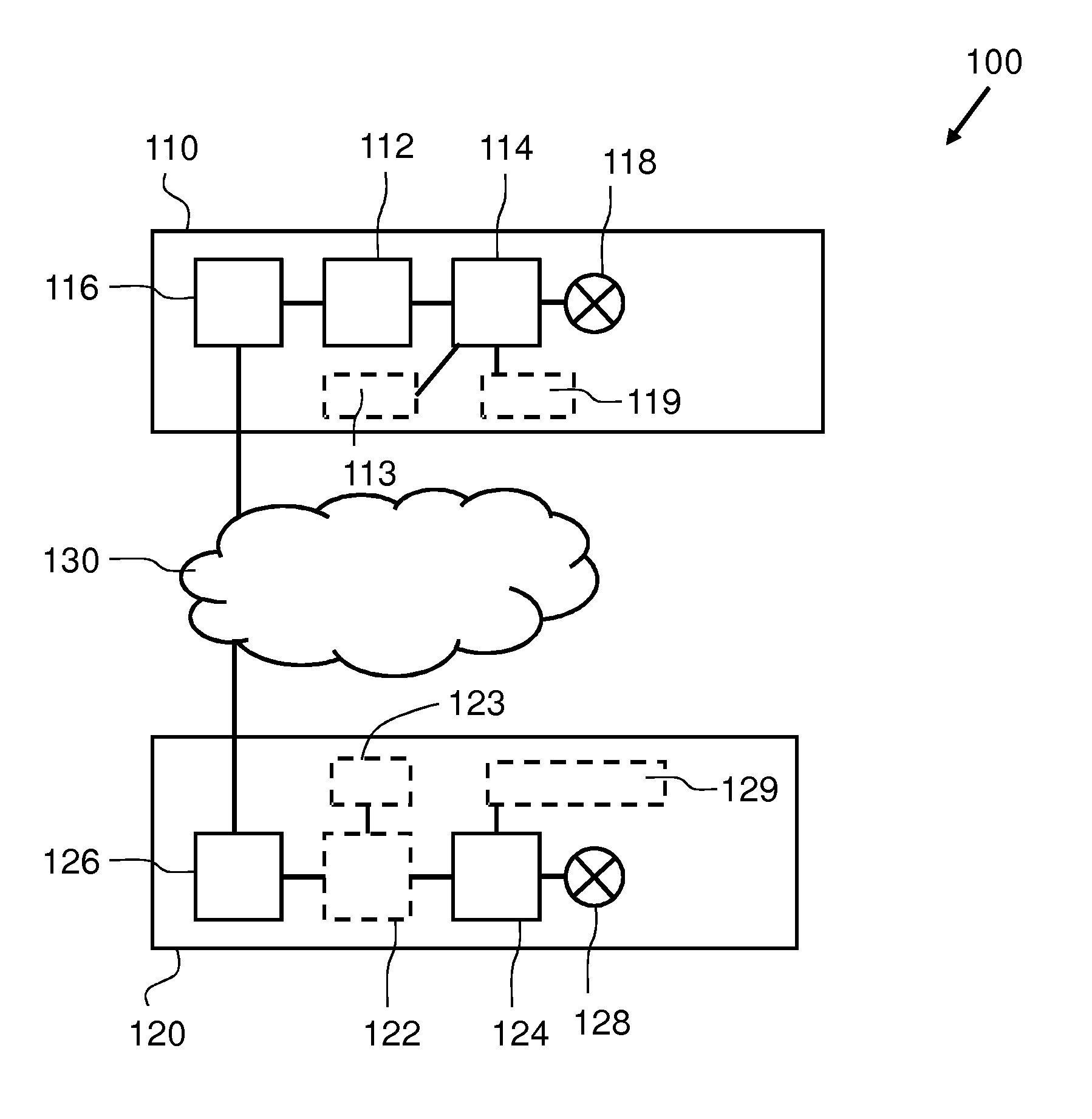
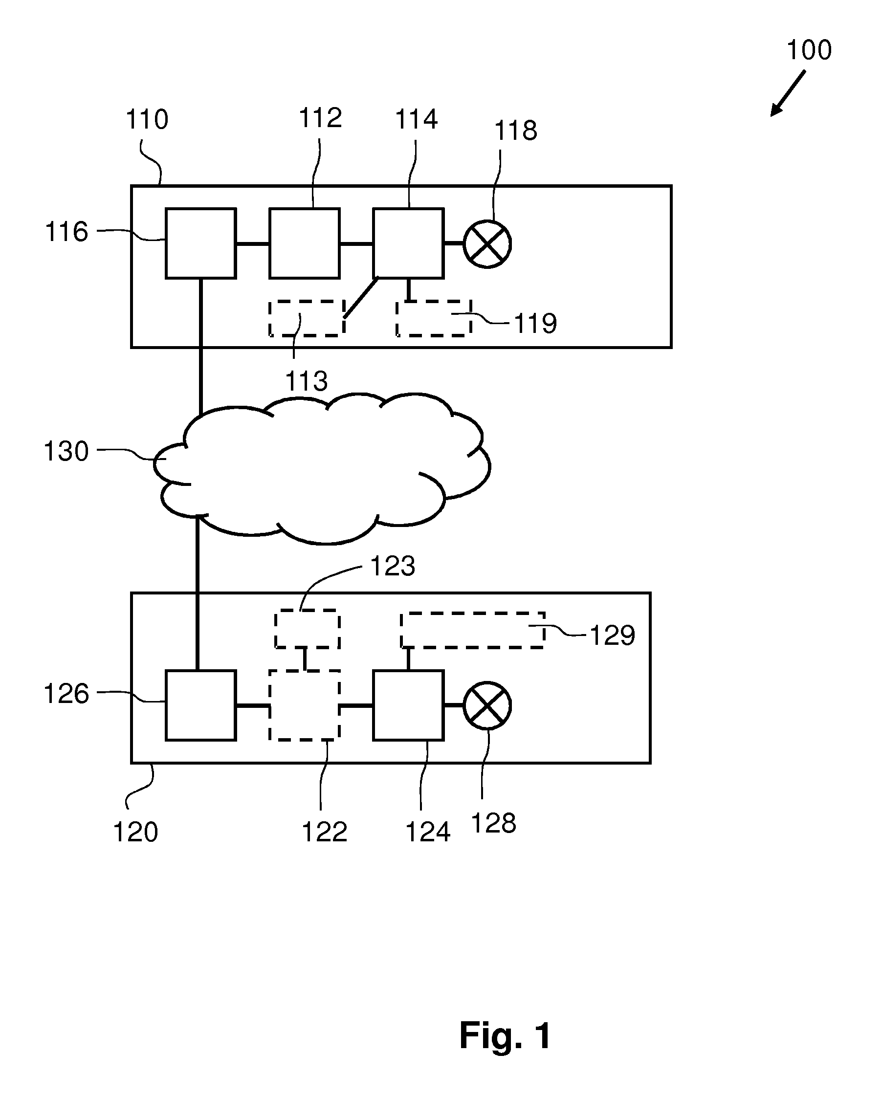
[0059]A first embodiment is shown in FIG. 1. FIG. 1 schematically shows an embodiment of a lighting system 100 according to the first aspect of the invention. The lighting system 100 may be used to illuminate an environment. The environment may be an indoor space or an outdoor space. The indoor space may be a room in a house, in an office, or, for example, a corridor of a building. The indoor space may also be a road-tunnel. The outdoor space may, for example, be a road or a parking lot.

[0060]The lighting system 100 comprises a particular lighting module 110 and a neighboring lighting module 120 which are coupled to each other via a network 130. Both lighting modules 110, 120 comprise a light source 118, 128 for emitting light, a programmable controller 114, 124 for controlling an operation of the light source and a network interface 116, 126 for allowing the programmable controller to communicate via the network with other devices of the lighting system. The lighting modules 110, 1...


PUM


Abstract

A lighting system (100) for illuminating an environment and a method of starting the installation of a program on a programmable controller of a lighting module are provided. The lighting system (100) comprises a particular lighting module (110), a neighboring lighting module (120) and an installation decision generator (112). A portion of the environment is illuminated by both lighting modules (110, 120). Both lighting modules (110, 120) have a programmable controller (114, 124) and may receive a program via a network interface for installation on the programmable controller (114, 124). The installation decision generator (112) decides whether the installation of the program on the particular lighting module (110) may start, based on operational information as to whether the light emission capabilities of the neighboring lighting module (120) enable illumination of the portion of the environment to be sufficiently close to a desired illumination of the portion.

Description

CROSS-REFERENCE TO PRIOR APPLICATIONS[0001]This application is the U.S. National Phase application under 35 U.S.C. §371 of International Application No. PCT / EP14 / 061559, filed on Jun. 4, 2014, which claims the benefit of European Patent Application No. 13170353.0, filed on Jun. 4, 2013. These applications are hereby incorporated by reference herein.FIELD OF THE INVENTION[0002]The invention relates to a lighting system comprising lighting modules provided with a programmable controller.[0003]The invention further relates to a method of starting an upgrade of a program of a programmable controller of a particular lighting module.BACKGROUND OF THE INVENTION[0004]In modern lighting systems, lighting modules may comprise a programmable controller which controls the operation of the lighting module. This operation comprises, for example, the controlling of the light emission of a light source of the lighting module. The lighting modules with the programmable controller may be connected to...

Claims


Application Information

Patent Timeline
Patent Type & Authority Patents(United States)
IPC IPC(8): H05B37/02
CPCH05B37/029H05B37/0227H05B37/0245H05B47/10H05B47/115H05B47/175Y02B20/40H05B47/155
Inventor VANGEEL, JURGEN MARIOCOOPMANS, MARKUS WILHELMUS MARIARIETMAN, WIJNAND JOHANNESVAN BEURDEN, JOHN ANDRE
Owner SIGNIFY HLDG BV
Why Eureka
Try Eureka