A kind of injection mold and its straight ejection mechanism

An injection mold, straight top technology, applied in the field of straight top mechanism, can solve the problems of large friction and wear between the elastic needle and the core, reduce the service life of the mold, etc., and achieve the effect of avoiding extrusion wear, simplifying the design, and avoiding damage.

Inactive Publication Date: 2018-06-08
台州市黄岩亿德塑模有限公司
View PDF6 Cites 2 Cited by
  • Summary
  • Abstract
  • Description
  • Claims
  • Application Information

AI Technical Summary

Problems solved by technology

The spring pin contacts the surface of the bump fixed on the core during the rising process of the ejector rod. When the spring pin moves to the groove on the bump, it pushes into the groove under the action of the spring, so that the spring pin and the workpiece Detachment completes the buttoning and demoulding process of the workpiece. In this way, the return of the spring pin depends on the action of the spring, and the ejection of the spring pin depends on the inner wall of the extrusion core, which makes the friction and wear between the spring pin and the core larger. Reduced service life of the entire mold

Method used


Image

  • A kind of injection mold and its straight ejection mechanism
  • A kind of injection mold and its straight ejection mechanism
  • A kind of injection mold and its straight ejection mechanism

Examples


Embodiment Construction

[0037] The present invention will be described in further detail below in conjunction with the accompanying drawings.

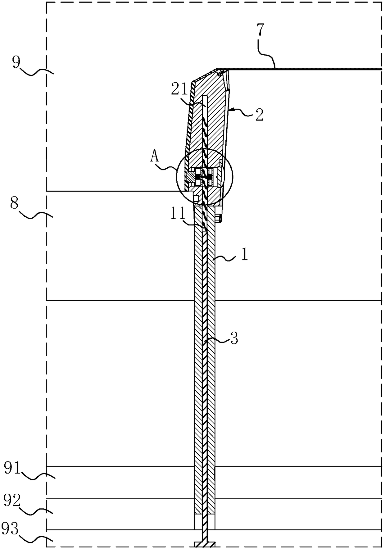
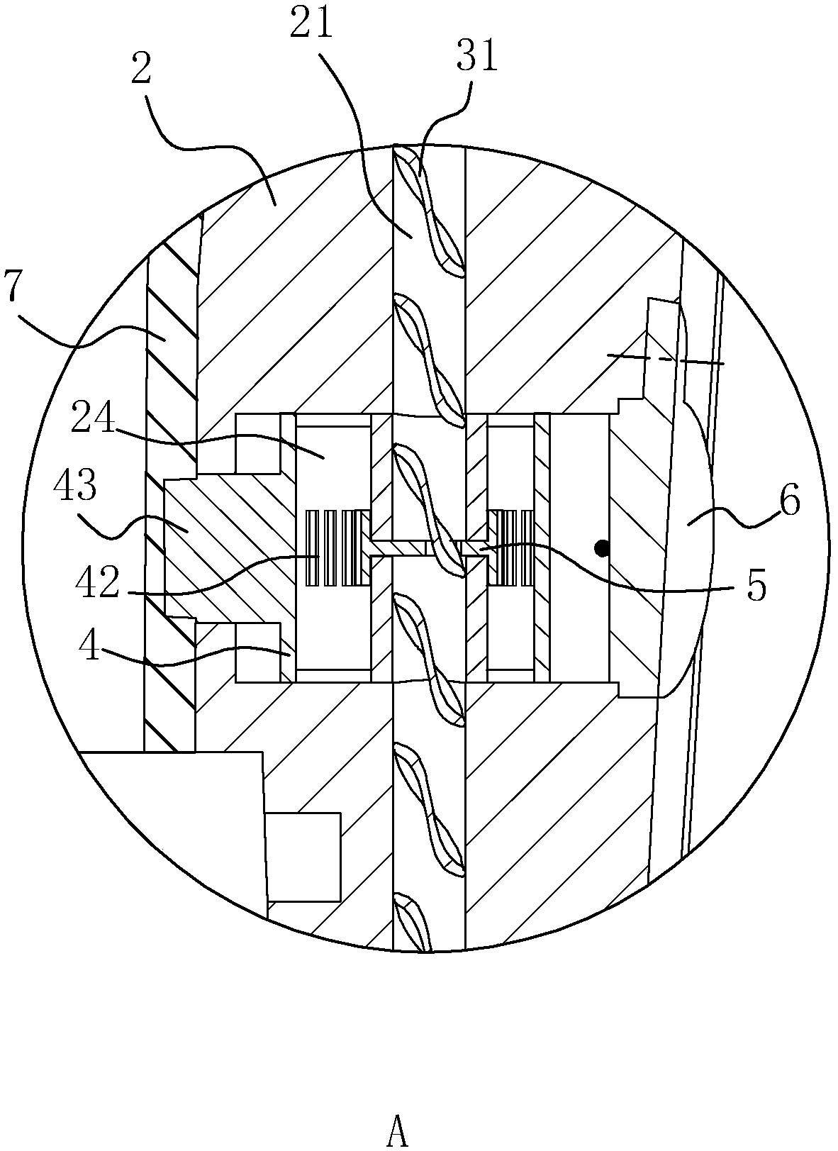
[0038] see figure 1 , an injection mold, comprising a core 8, a cavity 9, a ejector plate 91, a push plate 92, a lower fixing plate 93 and a straight ejector mechanism located inside the mold, the straight ejector mechanism includes a straight ejector rod 1 and is fixed on a straight ejector The straight top block 2 on the top of the ejector rod 1 is slidably connected with the transmission rod 3 in the straight ejector rod 1 and the straight ejector block 2, and a first channel 11 is provided inside the straight ejector rod 1, and a second channel 11 is provided inside the straight ejector block 2. Channel 21, the first channel 11 communicates with the second channel 21, and the diameter of the first channel 11 and the second channel 21 are the same, the transmission rod 3 slides axially in the first channel 11 and the second channel 21, under normal conditi...


PUM


Abstract

The invention discloses an injection mold and a direct pushing mechanism thereof. A counter bore perpendicular o the moving direction of a direct pushing block is formed in the direct pushing block. A piston sliding in the axial direction is arranged in the counter bore. The end of the piston extends vertically to form an elastic needle. A through groove is formed in the piston. A sealed closed cavity is formed by the inner wall of the through groove and the inner wall of the counter bore. A gear is arranged in the cavity. A rack engaged with the gear is arranged at the groove bottom of the through groove. The direct pushing mechanism further comprises a transmission rod arranged in a direct pushing rod in a penetrating mode. The transmission rod is fixed to a bottom plate of the mold, and one section of the transmission rod is placed in the direct pushing block and penetrates through the gear. One section of the transmission rod is arranged to be a spiral section. A through hole engaged with the spiral section is formed in the middle of the gear. The demolding and withdrawing resetting processes of the direct pushing rod and the releasing and pushing resetting processes of the elastic needle in the direct pushing block are synchronous, extrusion abrasion of the elastic needle and a mold core is avoided, and the damping function is achieved to a certain extent in the demolding and withdrawing resetting processes, so that the demolding quality is improved, and the direct pushing block is prevented from being damaged.

Description

technical field [0001] The invention relates to the technical field of injection molds, in particular to a straight-top mechanism of an injection mold. Background technique [0002] With the development of injection molding technology, more and more injection molding products are used in our daily life. Many injection molding products are designed with through holes or blind holes for various purposes. When through holes or blind holes When the axial direction is inconsistent with the mold opening direction, the inner needle-drawing mechanism must be designed during mold design. [0003] As disclosed in the patent with the notification number CN 202011093U, a "plastic mold inclined top side pop-up device" includes an upper template and a lower template, the cavity is fixed under the upper template, and the mold foot and core are fixed on the lower template. There is a workpiece between the cavity and the core, and an thimble bottom plate and a thimble fixing plate are insta...

Claims


Application Information

Patent Timeline
Patent Type & Authority Patents(China)
IPC IPC(8): B29C45/33B29C45/44
CPCB29C45/33B29C45/332B29C45/4005B29C45/44
Inventor 李佳
Owner 台州市黄岩亿德塑模有限公司
Why Eureka
Try Eureka