Wheel torque distribution method based on forward-drive hub motors

A technology of wheel torque and distribution method, which is applied in the direction of electric vehicles, control drives, vehicle components, etc.

Active Publication Date: 2016-11-09
NANJING YUEBOO POWER SYST CO LTD
View PDF6 Cites 9 Cited by
  • Summary
  • Abstract
  • Description
  • Claims
  • Application Information

AI Technical Summary

Problems solved by technology

Although the above-mentioned patent application can minimize the power consumption of the car and achieve the best energy-saving effect, it cannot solve the problem of how to reduce tire wear and maintain vehicle stability during the form of the car, especially during the turning process.

Method used


Image

  • Wheel torque distribution method based on forward-drive hub motors
  • Wheel torque distribution method based on forward-drive hub motors
  • Wheel torque distribution method based on forward-drive hub motors

Examples


Embodiment Construction

[0044] The technical solutions in the embodiments of the present invention will be clearly and completely described below in conjunction with the accompanying drawings in the embodiments of the present invention. Obviously, the described embodiments are only some of the embodiments of the present invention, not all of them. All other embodiments obtained by persons of ordinary skill in the art based on the embodiments of the present invention belong to the protection scope of the present invention.

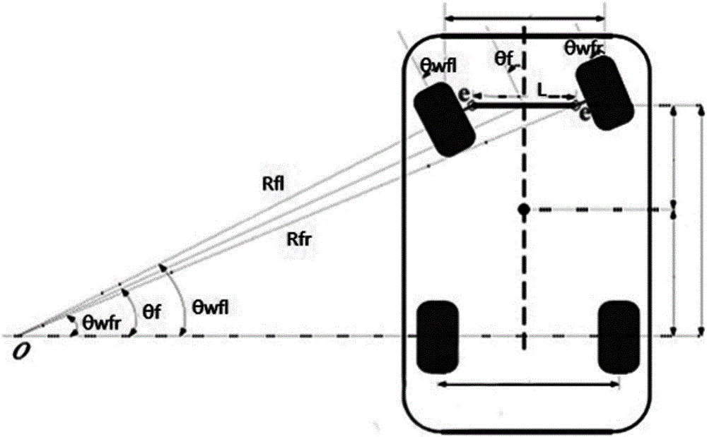
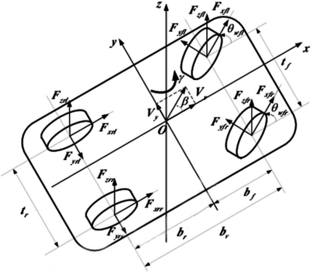
[0045] Such as Figure 1-2 As shown, a method for distributing wheel torque based on a front-drive in-wheel motor according to an embodiment of the present invention includes the following steps:

[0046] Step 1. Obtain the steering wheel angle θ by sensor measurement f ;

[0047] Step 2. Use the following formula to calculate the rotation angles of the drive wheels on the left and right sides respectively

[0048] b ...


PUM


Abstract

The invention discloses a wheel torque distribution method based on forward-drive hub motors. The rotating speed difference between two front wheels is worked out by measuring the rotating angle of a steering wheel, then the torque of the two front wheels is worked out, and accordingly the hub motors are controlled to output corresponding torque. The wheel torque distribution method based on the forward-drive hub motors has the beneficial effects that wheel torque can be reasonably distributed, and tire abrasion and energy loss are reduced.

Description

technical field [0001] The invention relates to the technical field of vehicle control, in particular to a method for distributing wheel torque based on a front-drive hub motor. Background technique [0002] With the continuous development of the electric vehicle industry, our requirements for vehicle performance are getting higher and higher, and the vehicle system that only relies on the powertrain of the traditional motor and gearbox has been difficult to meet our growing needs. In-wheel motor technology has also developed rapidly in recent years. The technology has become more and more mature, and its application has become more and more extensive. It has gradually caught up with other motors. [0003] The hub motor has a simple structure and is easy to use. Because it is directly installed in the hub of the tire, it occupies a very small space and is light in weight. It can be replaced with a hub motor without much modification to the original vehicle system. System, s...

Claims


Application Information

Patent Timeline
IPC IPC(8): B60W30/18B60W30/182B60L15/38
CPCB60L15/38B60W30/18145B60W30/18172B60W30/18181B60W30/182B60W2510/0604B60W2510/20B60W2520/28B60W2520/30B60W2720/30B60W2720/406
Inventor 李占江李麟李梦阳
Owner NANJING YUEBOO POWER SYST CO LTD
Why Eureka
Try Eureka