Dye vat cleaning device

A cleaning device and dyeing vat technology, which is applied in the field of textile printing and dyeing, can solve the problems of manual cleaning of dyeing vats, troubles, etc., and achieve the effect of convenient cleaning and improved efficiency

Inactive Publication Date: 2016-11-09
SHAOXING YONGLI PRINTING & DYEING ZHEJIANG
View PDF0 Cites 6 Cited by
  • Summary
  • Abstract
  • Description
  • Claims
  • Application Information

AI Technical Summary

Problems solved by technology

[0002] Existing dyeing vats need manual cleaning, which is very troublesome

Method used


Image

  • Dye vat cleaning device

Examples


Embodiment 1

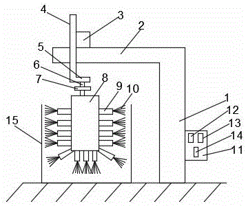
[0009] Such as figure 1 A kind of dye vat cleaning device shown, comprises column 1, and crossbar 2 is installed on described column 1, and stepping motor 3 is installed on described crossbar 2, and described stepping motor 3 and screw mandrel 4 are threadedly connected, so The lower end of the screw mandrel 4 is equipped with a bearing 5, the bearing 5 is connected to the motor 7 through the first rotating shaft 6, the output shaft of the motor 7 is connected to the second rotating shaft 8, and the surrounding, bottom and bottom edge of the second rotating shaft 8 are Support rods 9 are all installed, and a hairbrush 10 is installed on the top of the support rods 9. A control panel 11 is installed on the column 1, and a stepper motor lift switch 12 and a stepper motor drop switch are provided on the control panel 11. 13 and motor switch 14, described control panel 11 is connected with stepper motor 3, motor 7 lines respectively, and described hairbrush 10 stretches in the dye...


PUM


Abstract

The invention discloses a dye vat cleaning device which comprises an upright. A transverse rod is mounted on the upright, a stepping motor is mounted on the transverse rod and is in threaded connection with a screw, a bearing is mounted at the lower end of the screw and connected with a motor through a first rotating shaft, an output shaft of the motor is connected with a second rotating shaft, supporting rods are mounted on four sides of, at the bottom of and at the edge of the bottom of the second rotating shaft, and a hairbrush is mounted at the top of each supporting rod; a control panel is mounted on the upright, a stepping motor ascending switch, a stepping motor descending switch and a motor switch are arranged on the control panel, the control panel is in circuit connection with both the stepping motor and the motor, and the hairbrushes extend into a dye vat. The dye vat cleaning device can electrically clean the dye vat, so that trouble in manual cleaning is omitted and efficiency is improved; the dye vat cleaning device is adjustable in height, thereby bringing convenience to cleaning.

Description

technical field [0001] The invention relates to the field of textile printing and dyeing, in particular to a dye vat cleaning device. Background technique [0002] Existing dye vats need to be manually cleaned, which is very troublesome. Contents of the invention [0003] The purpose of the present invention is to provide a dyeing vat cleaning device, which can clean the dyeing vat electrically, save the trouble of manual cleaning, improve efficiency, and at the same time, the height can be adjusted to facilitate cleaning. [0004] In order to achieve the above object, the technical solution provided by the present invention is to include a column, a cross bar is installed on the column, a stepping motor is installed on the cross bar, the stepping motor is connected with the screw thread, and the wire The lower end of the rod is equipped with a bearing, the bearing is connected to the motor through the first rotating shaft, the output shaft of the motor is connected to th...

Claims


Application Information

Patent Timeline
Patent Type & Authority Applications(China)
IPC IPC(8): D06B23/30
CPCD06B23/30
Inventor 凌兴刚
Owner SHAOXING YONGLI PRINTING & DYEING ZHEJIANG
Why Eureka
Try Eureka