
Reinforcement trolleys suitable for construction in curved sections

A reinforced trolley and trolley technology, which is applied to shaft linings, tunnel linings, underground chambers, etc., can solve the problems of small working surface, low track utilization rate, slow walking speed, etc., to avoid derailment and improve two The effect of secondary utilization

Active Publication Date: 2018-08-31
GEZHOUBA GRP NO 2 ENG
View PDF6 Cites 0 Cited by
  • Summary
  • Abstract
  • Description
  • Claims
  • Application Information

AI Technical Summary

Problems solved by technology

[0003] The purpose of the present invention is to overcome the problems of low track utilization rate, small working surface and slow walking speed of existing trolleys in curved road construction, and to provide a trolley with a high universal rate, which makes the trolley travel fast and can meet the requirements of the trolley. The trolley passes through the turn and runs smoothly to the designated position, which is safe and suitable for the steel bar trolley in the construction of the turning section

Method used


Image

  • Reinforcement trolleys suitable for construction in curved sections
  • Reinforcement trolleys suitable for construction in curved sections
  • Reinforcement trolleys suitable for construction in curved sections

Examples


Embodiment Construction

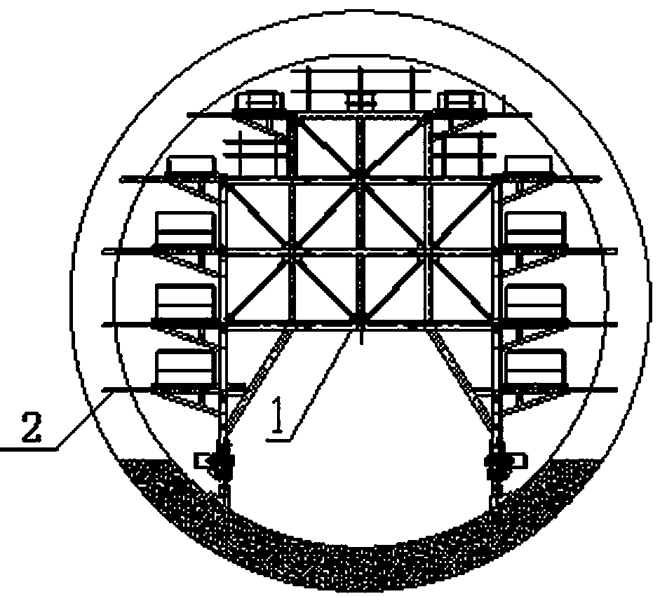
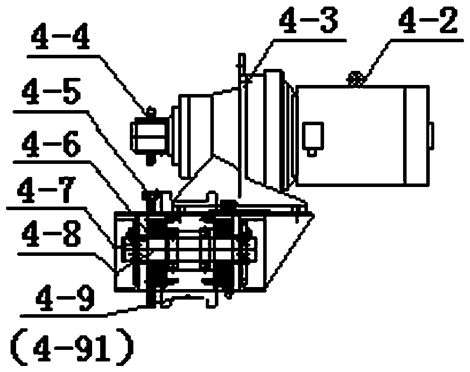
[0021] see figure 1 , figure 2 , this embodiment is applicable to the steel bar trolley for the construction of the turning section, including the steel bar trolley truss 1, the multi-layer side platforms 2 located on both sides of the steel bar trolley truss, the trolley ladder 3, the walking system 4, and the track 5.

[0022] see Figure 1 to Figure 4 , In the steel trolley truss 1, the vertical pole 1-1 is HW200x200, the beam 1-2 is HW200X200, the horizontal connecting beam 1-3 is 18, the vertical pole 1-4 is 18, and the shear brace 1-5 is 75× 75×5 angle steel, each single piece is connected by M16X60 bolts. There are 8-shaped diagonal braces 1-6 between the bottom beam and the vertical pole, and the material is HW200X200. Bottom longitudinal beams 1-7 are made of double 30 channel steel assembly welding, and there are multiple sets of connecting holes 1-8 on the bottom longitudinal beams. According to the difference in curvature and turning radius, the connecting seat...


PUM


Abstract

The invention provides a steel bar trolley suitable for construction of a turning section. The steel bar trolley comprise a steel bar trolley truss, a plurality of layers of side face platforms located on the two sides of the steel bar trolley truss correspondingly, trolley crawling ladders, traveling systems and a rail. A plurality of sets of connecting holes are formed in two corresponding bottom longitudinal beams of the steel bar trolley truss. Each traveling system comprises a traveling longitudinal beam, inner traveling steel wheels and outer traveling steel wheels, wherein the inner traveling steel wheels and the outer traveling steel wheels are installed on the traveling longitudinal beam and driven by a motor through a sprocket-chain transmission mechanism to travel on the rail, and the diameter of the inner traveling steel wheels is smaller than that of the outer traveling steel wheels. Traveling wheel hinging seats are hinged to the traveling longitudinal beams through rotary shafts. Connecting seats are installed at the tops of the traveling wheel hinging seats. A plurality of connecting holes are formed in the connecting seats. The connecting seats are connected with the bottom longitudinal beams in the steel bar trolley truss by means of connectors through the connecting holes in the connecting seats and connecting holes in the bottom longitudinal beams. According to the steel bar trolley, the universality is high, the traveling speed of the trolley is high, the requirement that the trolley operates to a specific position smoothly through turning can be met, and safety is achieved.

Description

Technical field: [0001] The invention belongs to the technical field of water conservancy and hydropower engineering construction, and is suitable for the binding construction of steel bars in tunnels of hydropower stations, especially for the construction with turning sections, and can also be used for steel trolleys used for binding steel bars in the turning lining sections of tunnels in railways, highways, and water conservancy and hydropower projects. . Background technique: [0002] In the tunnel construction of highways, railways, and hydropower stations, there are often turning sections in the tunnel structure, and the turning curvature of the turning section is different. The trolley must pass through the turning section. According to the conventional method: ①The track is bent into a circular arc according to the curvature, which can only be used for a single The use of the project resulted in a low common rate; ②Shortening the length of a single set of steel trolle...

Claims


Application Information

Patent Timeline
Patent Type & Authority Patents(China)
IPC IPC(8): E21D11/10E21D11/40
CPCE21D11/107E21D11/40
Inventor 刘红岩曾良红饶昌福孙金鹏吉婷胡海袁勤凯杜坚孔瑞
Owner GEZHOUBA GRP NO 2 ENG
Learn More