Overrun clutch

A technology of overrunning clutches and pawls, which is applied in the field of clutches, can solve the problems of small transmission torque, short life of structural parts, and concentration of pawl contact stress, and achieve the effect of avoiding stress concentration

Active Publication Date: 2016-11-09
GUANGDONG UNIV OF TECH
View PDF7 Cites 11 Cited by
  • Summary
  • Abstract
  • Description
  • Claims
  • Application Information

AI Technical Summary

Benefits of technology

This patented technology describes an improved transmission mechanism for use within vehicles' braking systems. Overrun clutches have two covers plated onto one shaft supporting a central rotor wheel called the primary or main rotation ring. These covers allow the operation rods inside them to move backward while they revolve around their own axis. To prevent damage during high-speed movement, these mechanisms include springs attached to each other, allowing the movements to smoothly occur without any resistance. Additionally, certain features like ball bearings and rollers may further enhance performance.

Problems solved by technology

The technical problem addressed in this patented technology relates to reducing the strain on these component elements during use when transferring energy from one rotating member (the primary) into another without causing damage.

Method used


Image

  • Overrun clutch
  • Overrun clutch
  • Overrun clutch

Examples


Embodiment 1

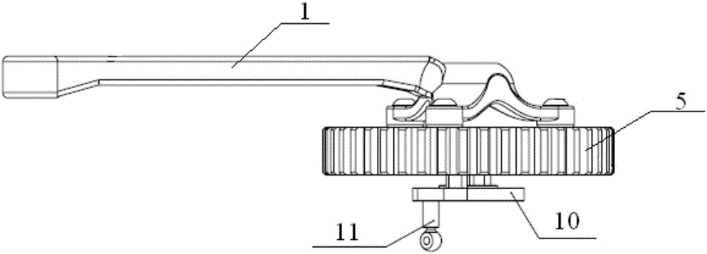
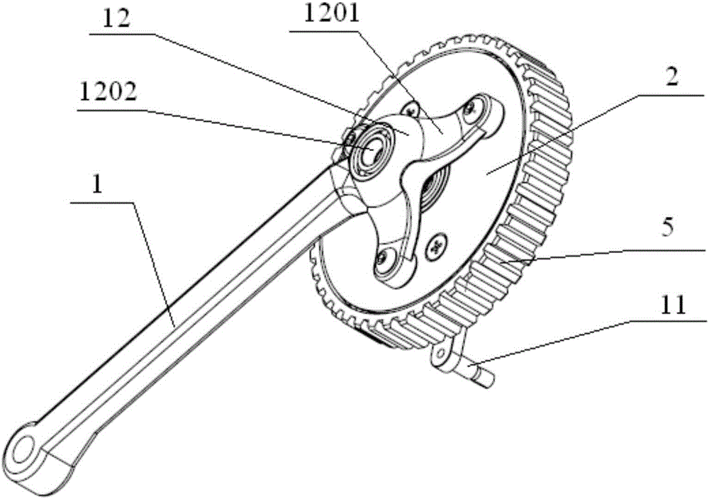
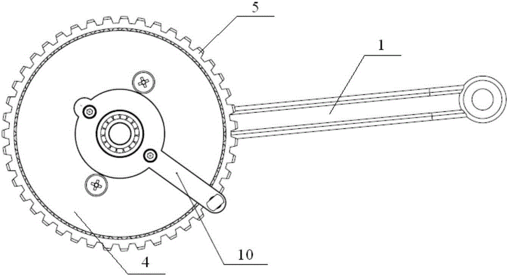
[0050] see Figure 1-14, The invention discloses an overrunning clutch, comprising: an operating rod 1, a first cover plate 2, a second cover plate 4, an intermediate rotating block 3, a rotating ratchet wheel 5 with internal and external teeth, and a pawl 6. Wherein, the first end of the operating rod 1 is used to bear the applied load, the second end of the operating rod 1 is connected with the first cover plate 2, the middle rotating block 3 is connected with one side of the first cover plate 2, and the second cover plate 4 Connected with the other side of the middle rotating block 3, the internal and external tooth rotating ratchet 5 is coaxial with the middle rotating block 3, and the internal and external tooth rotating ratchet 5 is installed between the first cover plate 2 and the second cover plate 4, and the internal and external tooth rotating ratchet There is a first installation track 14 for installing the ball 13 between the outer teeth 502 of the ratchet 5 and th...

Embodiment 2

[0058] In yet another embodiment of the present invention, the structure of the overrunning clutch in this embodiment is similar to that in the first embodiment, and the similarities will not be repeated, and only the differences will be introduced.

[0059] In the embodiment, it is specifically disclosed that a spring 7 is further arranged between the middle rotating block 3 and the ratchet 6 . Wherein, the spring 7 plays the role of tension and compression.

[0060] Further, the present invention discloses that the overrunning clutch also includes a connecting rod 8 and a nested chuck 9 rotatably connected to the connecting rod 8; the nested chuck 9 is rotatably connected to the second cover plate 4; There is a first groove 301; the connecting rod 8 swings in the first groove 301, and the first end of the connecting rod 8 is connected with the nested chuck 9, and the second end of the connecting rod 8 is connected with the pawl 6; the connecting rod 8 is in the Swinging in ...


PUM


Abstract

The invention discloses an overrun clutch. The overrun clutch comprises an operation rod, a first cover plate, a middle rotation block, a second cover plate, an internal-external tooth rotation ratchet wheel and a pawl, wherein a first end of the operation rod is used for bearing exerted loads, the first cover plate is connected to a second end of the operation rod, one surface of the middle rotation block is connected to the first cover plate, the second cover plate is connected to the other surface of the middle rotation block, the internal-external tooth rotation ratchet wheel is coaxial with the middle rotation block, an installation track used for installing balls is formed between external teeth of the internal-external tooth rotation ratchet wheel and internal teeth of the internal-external tooth rotation ratchet wheel, the first cover plate and the second cover plate are installed at the two ends of the balls inside the installation track in a supported mode, a first end of the pawl is connected to the middle rotation block in a rotating mode, and a second end of the pawl is arranged anticlockwise relative to the first end of the pawl and can mesh with the internal teeth of the internal-external tooth rotation ratchet wheel. According to the overrun clutch, force exerted on the internal-external tooth rotation ratchet wheel by the pawl is direct driving force instead of friction force, so that part abrasion is reduced, stress concentration is avoided, and a lever is formed among the pawl, the middle rotation block and the operation rod and can transmit large torque.

Description


Claims


Application Information

Patent Timeline
Owner GUANGDONG UNIV OF TECH
Why Eureka
Try Eureka