Heat supply load forecasting method based on a comprehensive temperature

A load and heat supply technology, applied in forecasting, renewable energy integration, instruments, etc., can solve the problems of not considering outdoor wind speed, solar radiation, indoor heat gain and heat supply, etc.

Active Publication Date: 2016-11-09
HARBIN INST OF TECH +1
View PDF2 Cites 19 Cited by
  • Summary
  • Abstract
  • Description
  • Claims
  • Application Information

AI Technical Summary

Benefits of technology

This patented technology helps calculate an accurate amount of electricity needed from different types of sources like pipes or houses based upon their specific characteristics such as size, shape, material properties etc., which makes it possible to save money while still providing more efficient power usage than what was previously used beforehand.

Problems solved by technology

This patented technical problem addressed in this patents relates to improving thermal management systems during peak hours when there are insufficient power supplies available at all times due to changes caused by factors like cloud cover overheated windows or poorly designed roofs.

Method used


Image

  • Heat supply load forecasting method based on a comprehensive temperature
  • Heat supply load forecasting method based on a comprehensive temperature
  • Heat supply load forecasting method based on a comprehensive temperature

Examples


specific Embodiment approach 1

[0050] Specific implementation mode one: the heating load forecasting method based on comprehensive temperature comprises the following steps:

[0051]Firstly, a building with multiple surfaces, each with different thermal properties, is simplified to an equivalent building with the same surface properties. Then convert all the buildings and all pipe networks within the range supplied by the heat source into a comprehensive equivalent building to obtain the equivalent thermal characteristic coefficient of the building. The heating load forecast is carried out on the basis of replacing the dry bulb temperature with the comprehensive temperature and considering the indoor heat gain, taking into account the solar radiation capacity absorbed by the outer surface of the wall, the long-wave radiation exchange between the building and the external environment, and the indoor heat gain. In order to solve the problem of traditional heating load prediction using dry bulb temperature, th...

specific Embodiment approach 2

[0109] Specific embodiment two: the difference between this embodiment and specific embodiment one is: Δt in the step four y By the formula (4) get:

[0110] Δt y = ρI y α e - - - ( 4 )

[0111] Wherein said ρ is solar radiation absorption coefficient, is checked by relevant manual; I y It is the predicted value of solar irradiance on the horizontal or vertical plane, which is obtained by statistical method according to the test data, and the unit is W / m 2 ; e is the heat transfer coefficient of the outer surface, according to the outdoor wind speed, it can be obtained from the relevant manual, and the unit is W / (m 2 ·°C).

specific Embodiment approach 3

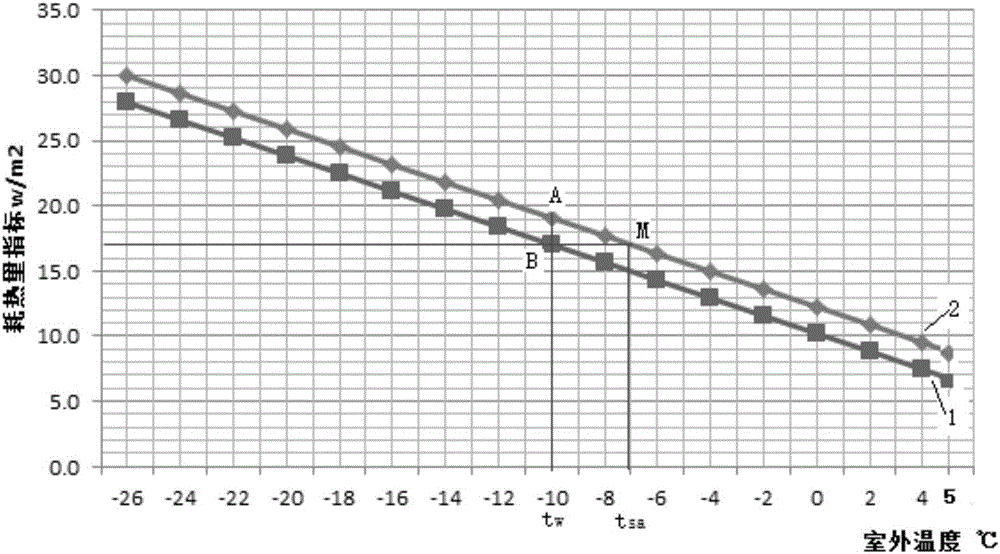
[0112] Specific embodiment three: the difference between this embodiment and specific embodiment one or two is that: in the step five, the predicted value of the comprehensive equivalent building heat consumption index is calculated according to formula (5), and can also be calculated according to t say check figure 1 Sure( figure 1 t in say The intersection point M with curve 2 is the predicted value):

[0113] q H y 1 = ( t n - t s a y ) 1000 × A 0 × γ - q I H - ...


PUM


Abstract

Provided is a heat supply load forecasting method based on a comprehensive temperature, relating to a heat supply load forecasting method aiming to solve the problem of excessive forecasted heat supply loads generated by a traditional prediction method. The heat supply load forecasting method comprises: first simplifying a building (each surface of the building having different heat characteristics) into an equivalent building with same surface characteristics; converting all buildings and pipe networks in the supply range of a heat source into a comprehensive equivalent building, and obtaining the equivalent thermal property coefficient of the building; and employing a comprehensive temperature to substitute a dry-bulb temperature, and considering indoor heat gains to forecast heat supply loads, and comprehensively considering the influence of factors such as a wall external surface solar radiation absorption capability, and exchange between a building and extraneous environment long wave radiation, and indoor heat gains on heat supply loads. The heat supply load forecasting method solves the problems of a higher forecasted heat supply amount and energy waste caused when a traditional method does not consider the influence of solar radiation, outdoor wind speed and indoor heat gain building energy consumption, and can be applied to the heat supply load forecasting field.

Description


Claims


Application Information

Patent Timeline
Owner HARBIN INST OF TECH
Why Eureka
Try Eureka