Upper locking fuse with externally insulated fuse tube

An external insulation and fuse tube technology, applied in emergency protection devices, electrical components, circuits, etc., can solve the problems of easy arcing, incomplete disconnection, line faults, etc., and achieve the effect of reliable ejection and avoidance of discharge phenomenon.

Inactive Publication Date: 2016-11-09
铁岭市世纪电力设备有限公司
View PDF8 Cites 0 Cited by
  • Summary
  • Abstract
  • Description
  • Claims
  • Application Information

AI Technical Summary

Problems solved by technology

This patent has the following defects: 1. It is impossible to determine where the fuse first fuses. If the fuse occurs at the bottom end, the residual fuse on the upper part and the lead-out wire in the lower outlet are relatively close to each other, which is easy to generate arcs, resulting in Line failure; 2. The pop-up structure of this patent is unreasonable. Once the lower fuse tube is not completely popped out, the springs left in the insulating ceramic body will be used as conductors, which will easily cause incomplete breaking and cause losses.

Method used


Image

  • Upper locking fuse with externally insulated fuse tube
  • Upper locking fuse with externally insulated fuse tube
  • Upper locking fuse with externally insulated fuse tube

Examples


Embodiment Construction

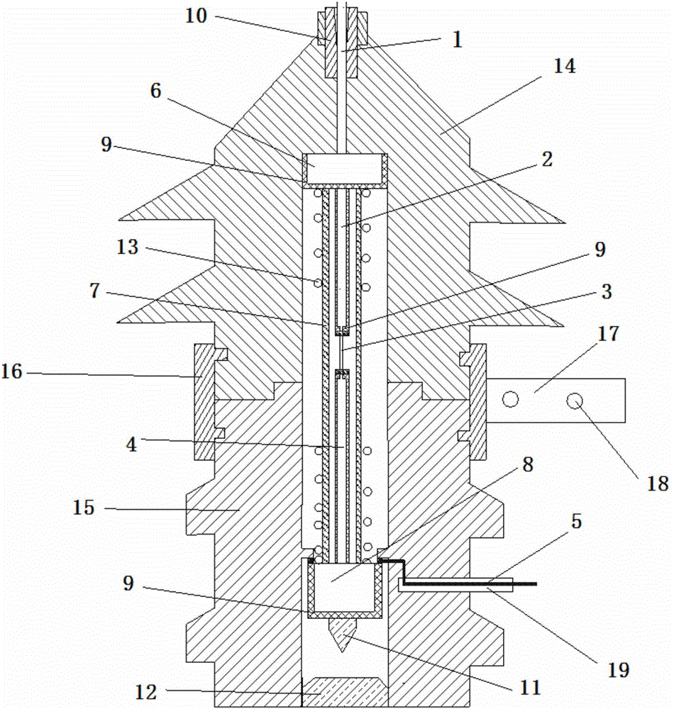
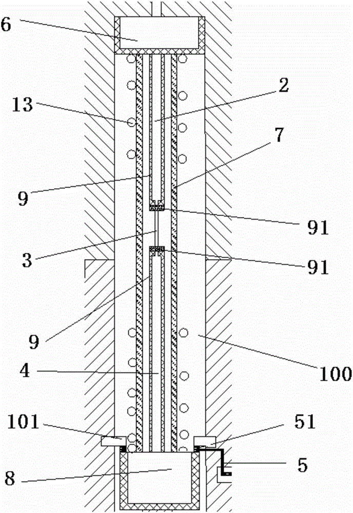
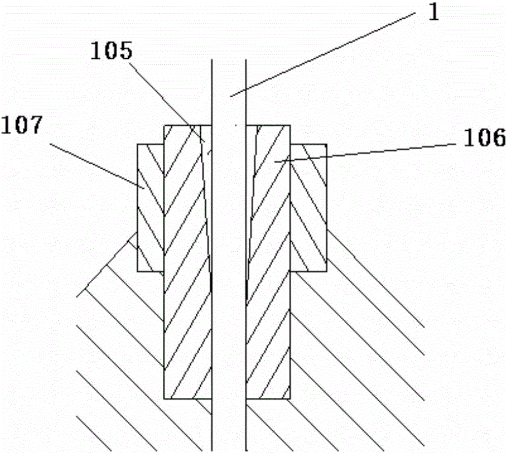
[0009] The present invention is specifically described below in conjunction with accompanying drawing, as figure 1 , figure 2 As shown, the present invention includes an insulating porcelain body and a fuse tube arranged in the axial cavity 100 of the insulating porcelain body. The insulating porcelain body includes two parts: an upper insulating porcelain body 14 and a lower insulating porcelain body 15. The insulating porcelain body The top of the porcelain body is provided with a locking device 10; as image 3 As shown, the locking device 10 includes a jacket 106 fixed in the groove on the top of the insulating porcelain body, the outside of the jacket 106 is provided with threads, and a wedge-shaped through hole 105 is arranged in the middle; the lead-out line 1 of the upper fuse tube 6 Through the wedge-shaped through hole 105; the clamping nut 107 is arranged outside the jacket 106, and the inner diameter of the clamping nut 107 is smaller than the outer diameter of th...


PUM


Abstract

The invention discloses an upper locking fuse with an externally insulated fuse tube. A locking device is arranged on the top of an insulating porcelain body, and a fuse is fixedly connected with a wiring terminal of a lower fuse tube, passes through an upper fuse tube and is fixed on the upper end of the insulating porcelain body through the locking device. A fusing portion with a small diameter is arranged on the fuse at the position where a central fuse tube is situated, fire-proof caps are arranged on the two ends of the fusing portion, and the thermal shrinking insulating layers sleeve the fuses between the fire-proof caps and the upper fuse tube and the lower fuse tube. Springs are arranged in an axial inner cavity between the upper fuse tube and the lower fuse tube, and a punching head is fixed to the bottom of the lower fuse tube. A plug is arranged on the bottom of an axial inner cavity of the insulating porcelain body. The fuse being fused is in an insulating state to prevent discharging phenomenon due to bad fusing position. The fuse tubes directly compress springs, and the punching head destroys sealing plug on the bottom of the insulating porcelain body, thereby ensuring reliably springing out of the lower fuse tube.

Description

technical field [0001] The invention relates to the technical field of power equipment, in particular to a fuse. Background technique [0002] Spray type fuse is to install the melt in the insulating tube made of solid gas-generating material. Solid gas-generating materials can be made of electrical anti-white cardboard or plexiglass materials. When the short-circuit current passes through the melt, the melt will be fused immediately to generate an arc, and the high-temperature arc will quickly decompose the solid gas-producing material to generate a large amount of high-pressure gas, so that the ionized gas will be ejected at both ends of the tube with an arc, and a great sound and light will be emitted. And when the AC current crosses zero, the arc is extinguished and the current is broken. Chinese patent application number 201310538197.X discloses a fuse, the fuse tube is arranged inside the insulating ceramic body, and the upper contact electrode and the lower contact ...

Claims


Application Information

Patent Timeline
IPC IPC(8): H01H85/05H01H85/165
CPCH01H85/05H01H85/165
Inventor 李颖王晓利汪德成杨海洪
Owner 铁岭市世纪电力设备有限公司
Why Eureka
Try Eureka