Automatic design method of drilling jig and tool for machining multi-lug-flake component holes

An automatic design and processing drilling technology, which is applied in metal processing equipment, drilling/drilling equipment, and drilling templates for workpieces, etc., can solve problems such as cumbersome communication and coordination, low efficiency, and delays in the production progress of parts

Active Publication Date: 2016-11-16
SHENYANG AIRCRAFT CORP
View PDF6 Cites 6 Cited by
  • Summary
  • Abstract
  • Description
  • Claims
  • Application Information

AI Technical Summary

Problems solved by technology

Due to the discontinuous deep hole structure of multi-lugs, and high requirements on coaxiality and hole diameter, this type of parts needs to be guided by the positioning of the drilling mold, and the machining of the coaxial holes of the multi-lugs is completed by means of tool drilling, expansion and reaming. The following problems exist in the tooling tool design stage: First, the three aspects of part processing design, tooling drilling mold design and tooling tool design are completed by technicians from three different departments, and the communication and coordination between them is cumbersome and inefficient; Due to professional differences and other reasons, it often occurs that the designed tools, drilling jigs and processed parts cannot match each other, and the problems are difficult to expose before processing. If problems occur during the processing, the repair of the cutting tools and drilling jigs will seriously delay the parts. production progress

Method used


Image

  • Automatic design method of drilling jig and tool for machining multi-lug-flake component holes
  • Automatic design method of drilling jig and tool for machining multi-lug-flake component holes
  • Automatic design method of drilling jig and tool for machining multi-lug-flake component holes

Examples


Embodiment

[0051] Embodiment Drilling template and tool automatic design method for hole processing of multi-lug parts

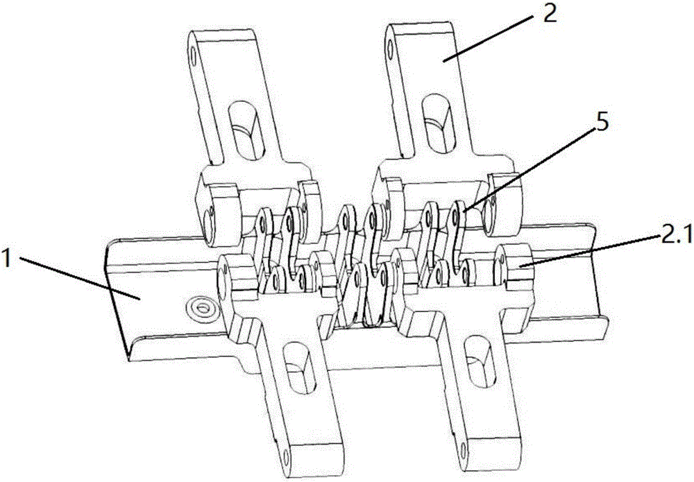
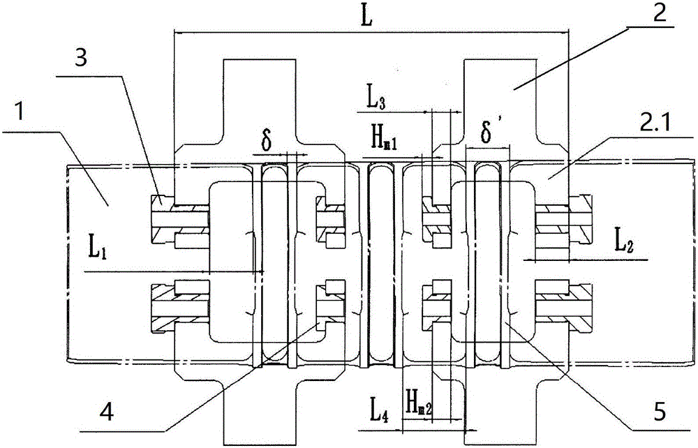
[0052] in such as figure 1 The automatic design of the drilling jig and tool during the preparation process of the multi-lug part hole processing process shown in the figure includes the following steps,

[0053] 1) Standard form database. Such as figure 1 with 2 The main structure of the drill template shown includes a drill template 2, a quick-change drill sleeve 3 and a plum blossom sleeve 4. The drill template 2 has two oppositely arranged template pieces 2.1, wherein the quick-change drill sleeve 3 is respectively assembled at the head and tail of the drill template body. The two ends are the template sheet 2.1 on the outermost side of the first drilling template 2 relative to the main body of the drilling template and the outermost template sheet 2.1 of the last drilling template 2 relative to the main body of the drilling template. The plum blossom sleeve 4 i...


PUM


Abstract

The invention discloses an automatic design method of a drilling jig and a tool for machining multi-lug-flake component holes. The automatic design method comprises the following steps that (1) a data base is formed according to aviation standards; (2) the holes in all lug flakes of a component are identified; (3) a main structure of the drilling jig is preliminarily designed; (4) design parameters of a twist drill are determined; (5) design parameters of an expanding drill are determined; (6) design parameters of a reamer are determined; (7) the specific size of the drilling jig is calculated; and (8) a three-dimensional mathematical model is generated. The automatic deign method depends on the component structure to complete automatic overall design of the drilling jig and the tool, so that the component, the tool and the drilling jig are matched with one another, the coordination problem is solved, and the effect that the component is machined successfully is ensured.

Description

technical field [0001] The invention relates to an automatic design method of drilling molds and tools for multi-lug part hole processing, which is mainly used for the automatic design of drilling molds and cutting tools in the preparation process of multi-lug part hole processing technology, and can be widely applied to deep holes with multi-lug parts In the processing of structural parts, it can significantly improve the efficiency and coordination of drilling mold and tool design, and create convenient conditions for subsequent processing and production. Background technique [0002] In the design of aircraft structure, hinge parts play the role of rotation and transmission, which can drive the overall movement of the wing surface, and are widely used. Due to the intermittent deep hole structure of multi-lugs, and high requirements for coaxiality and aperture size accuracy, it is necessary to use the positioning guide of the drilling mold, and complete the processing of t...

Claims


Application Information

Patent Timeline
Patent Type & Authority Applications(China)
IPC IPC(8): B23B47/28B23B51/02B23B51/00G06F17/50
CPCB23B47/28B23B51/0018B23B51/02B23D77/00G06F30/17
Inventor 常剑姜晓伟
Owner SHENYANG AIRCRAFT CORP
Why Eureka
Try Eureka