Self-locking clamping mechanism of clamp

A clamping mechanism and self-locking technology, used in manufacturing tools, auxiliary devices, auxiliary welding equipment, etc., can solve the problems of occupying space and increasing costs, and achieve simple structure, large opening angle, clamping force, stability, etc. Good results

Inactive Publication Date: 2016-11-16
WUXI SUNDA INTELLIGENT AUTOMATION & ENG COMPANY
View PDF6 Cites 8 Cited by
  • Summary
  • Abstract
  • Description
  • Claims
  • Application Information

AI Technical Summary

Problems solved by technology

[0002] The clamping mechanism of the fixture is often installed in places with special structural needs. It must have a large opening angle to facilitate picking up parts and a greater clamping force to reduce the deformation during welding, but it must be replaced by a large bore and stroke. Cylinder method to achieve large opening angle and clamping force, and this method increases the cost and also takes up corresponding space

Method used


Image

  • Self-locking clamping mechanism of clamp
  • Self-locking clamping mechanism of clamp
  • Self-locking clamping mechanism of clamp

Examples


Embodiment Construction

[0014] The present invention will be further described below in conjunction with specific examples.

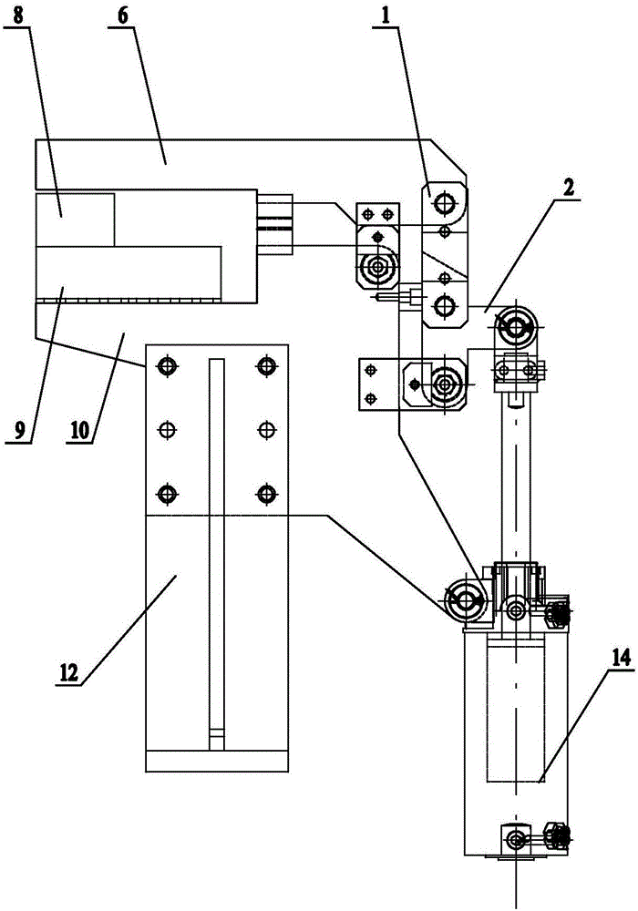
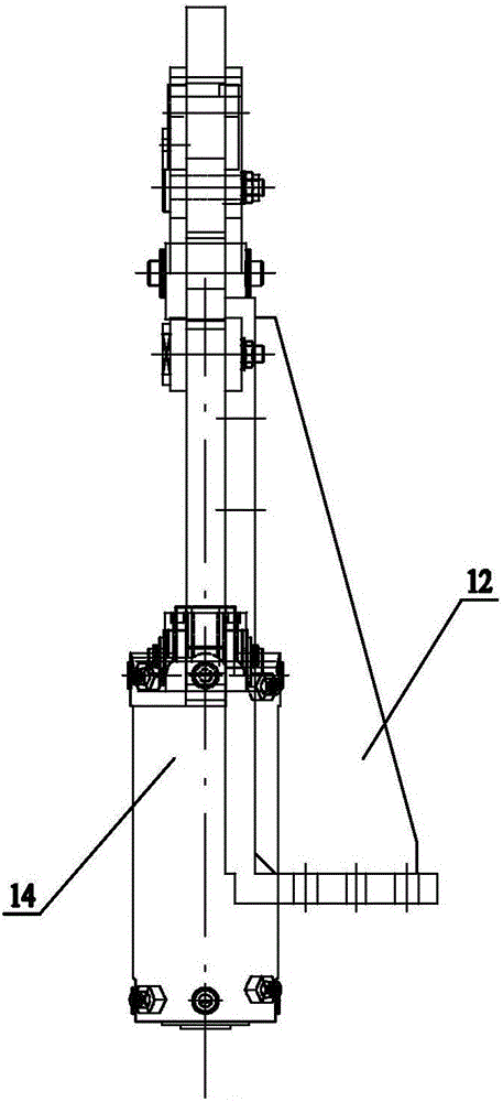
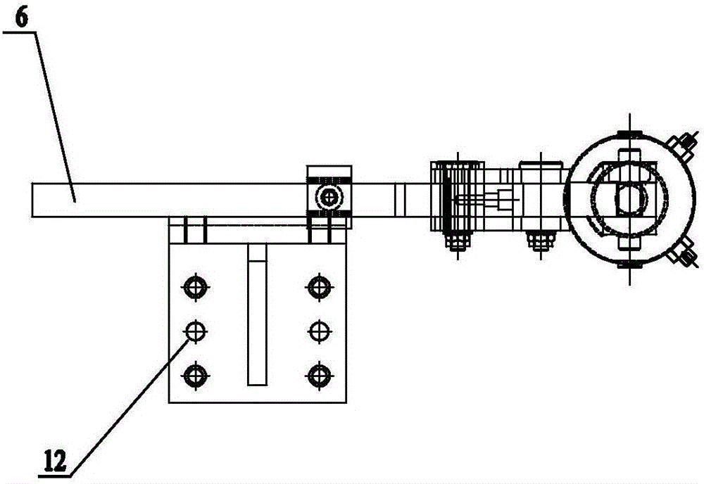
[0015] The clamping mechanism of the self-locking fixture includes a first self-locking block 1, a second self-locking block 2, a limit post 3, a first splint 4, a pressure head 6, a second splint 7, a pressure block 8, and a support block 9 , connecting plate 10, lower limit block 11, base 12 and upper limit block 15, the first self-locking block 1 has a first hinge point and a second hinge point, the second self-locking block 2 has a first hinge point, a second hinge point point and the third hinge point, three hinge points of the second self-locking block 2 form a triangle;

[0016] On the base 12, a connecting plate 10 is fixed, on the connecting plate 10, a second clamping plate 7 is hinged by a pin shaft, on the second clamping plate 7, a pressure head 6 is welded, and on the connecting plate 10, the first clamping plate 4, limiter Position post 3, support block 9 and l...


PUM


Abstract

The invention relates to a self-locking fixture clamping mechanism. A connecting plate is fixed on the base, a second clamping plate is hinged on the connecting plate through a pin shaft, a pressure head is welded on the second clamping plate, and a connecting plate is fixed on the connecting plate. The first splint, the limit column, the support block and the lower limit block, the first hinge point of the second self-locking block is hinged on the first splint through the pin shaft, and the second hinge point of the second self-locking block is connected to the first self-locking block. The first hinge point of the block is hinged through the pin shaft, the second hinge point of the first self-locking block is hinged with the rear end of the indenter through the pin shaft, the first self-locking block cooperates with the limit column, and the front end of the indenter A briquetting block is fixed, and the briquetting block cooperates with the support block. An upper limit block is fixed at the middle part of the lower surface of the pressure head, and the upper limit block cooperates with the lower limit block. The invention can realize large opening angle and clamping force without increasing the cylinder stroke, and the invention has simple structure, low cost and good stability.

Description

technical field [0001] The invention relates to a fixture clamping mechanism, in particular to a self-locking fixture clamping mechanism. Background technique [0002] The clamping mechanism of the fixture is often installed in places with special structural needs. It must have a large opening angle to facilitate picking up parts and a greater clamping force to reduce the deformation during welding, but it must be replaced by a large bore and stroke. The cylinder method is used to achieve a large opening angle and clamping force, and this method increases the cost and also occupies a corresponding space. Contents of the invention [0003] The purpose of the present invention is to overcome the shortcomings of the prior art and provide a self-locking fixture clamping mechanism that does not need to increase the stroke of the cylinder, has a simple structure, low cost and good stability. [0004] According to the technical solution provided by the present invention, the cla...

Claims


Application Information

Patent Timeline
Patent Type & Authority Applications(China)
IPC IPC(8): B23K37/04
CPCB23K37/0443
Inventor 高建飞吴华东
Owner WUXI SUNDA INTELLIGENT AUTOMATION & ENG COMPANY
Why Eureka
Try Eureka