
Detection worktable device

A technology for detecting workbenches and support platforms, which is applied to workbenches, manufacturing tools, etc.

Active Publication Date: 2016-11-16
涟水县苏杭科技有限公司
View PDF8 Cites 2 Cited by
  • Summary
  • Abstract
  • Description
  • Claims
  • Application Information

AI Technical Summary

Problems solved by technology

Some existing devices are difficult to solve the above problems at the same time

Method used


Image

  • Detection worktable device
  • Detection worktable device

Examples


Embodiment Construction

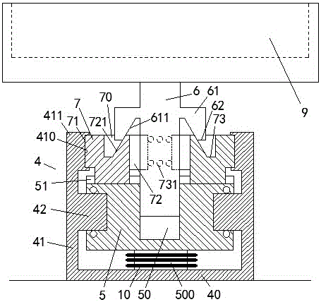
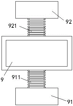
[0008] Combine below Figure 1-2 The present invention will be described in detail.

[0009] The detection workbench device according to the embodiment includes a product support platform 9, a support column 6 fixedly connected to the bottom of the product support platform 9, and a base device 4, and the base device 4 includes two left-right symmetrically arranged Side riser 41 and the base plate 40 that connects two side risers 41, the bottom of each side riser 41 is fixed with protruding part 42, and the top of described base plate 40 is fixed with driving motor 500, and the rotating bearing seat 5 strides The two protruding parts 42 are rotatably supported, and the middle position of the bottom of the rotating bearing seat 5 is power-coupled with the output shaft of the driving motor 500. The casing surface of the driving motor 500 is provided with three The heat dissipation fins 10 above, the heat dissipation fins 10 are used to absorb and dissipate the heat generated by ...


PUM


Abstract

A detection worktable device comprises a product supporting table (9), a supporting column (6) fixedly connected with the bottom of the product supporting table (9) and a base device (4). The base device (4) comprises two side vertical boards (41) symmetrically arranged left and right and a bottom board (40) connected with the two side vertical boards (41). A protruding part (42) is fixedly arranged at the bottom of each side vertical board (41). A drive motor (500) is fixedly arranged at the top of the bottom board (40). A rotary bearing seat (5) strides over the two protruding parts (42) to be rotationally supported. The middle position of the bottom of the rotary bearing seat (5) is in power connection with an output shaft of the drive motor (500).

Description

technical field [0001] The invention relates to the field of product testing, in particular to a testing workbench device. Background technique [0002] In the assembly line production process of the product, it is often necessary to test the product after the finished product. For some specific products, manual inspection is required after machine inspection to ensure product quality. Since the manual detection of the product needs to detect all orientations and angles of the product, it is necessary to make the product have a degree of freedom of rotation in a supported state. However, when the product is placed on the automation equipment, it is necessary to lock the product support table in rotation to avoid position errors. Some existing devices are difficult to solve the above problems simultaneously. Contents of the invention [0003] The object of the present invention is to provide a testing workbench device, which can overcome the defects in the prior art. ...

Claims


Application Information

Patent Timeline
IPC IPC(8): B25H1/00B25H1/14
CPCB25H1/00B25H1/14
Inventor 邱美好
Owner 涟水县苏杭科技有限公司
Learn More