Rolling mechanism of tread winding machine

A winding machine and rolling technology, applied in the field of automatic tread winding rubber, can solve the problems of low bonding density, uneven thickness of rubber bonding, complex structure of film winding and rolling mechanism, etc., and reduce the amount of air bubbles. Effect

Pending Publication Date: 2016-11-16
SICHUAN YUANXING RUBBER
View PDF13 Cites 0 Cited by
  • Summary
  • Abstract
  • Description
  • Claims
  • Application Information

AI Technical Summary

Problems solved by technology

[0005] The invention aims to solve the problems of complex structure of the film winding and rolling mechanism of the existing tread winding machine, uneven thickness of the rubber material on the tread, low density of bonding, and easy occurrence of air bubbles and delamination of the tire. A new film winding and rolling mechanism of the tread winding machine. The structure of the film winding and rolling mechanism is simple, and the pressing is carried out at the same time as the glue is applied. The pressing density is high, and the quality of the tire product after retreading is guaranteed.
Contents of the invention
[0006] The invention aims to solve the problems of complex structure of the rolling mechanism of the existing tread automatic winding machine, uneven thickness of the rubber material on the tread, low bonding density, and easy occurrence of air bubbles and delamination of the tire. A new method is proposed. The rolling mechanism of the tread winding machine, the rolling mechanism of the tread winding machine has a simple structure, and the pressing is carried out at the same time as the glue is applied, the pressing density is high, and the quality of the tire product after retreading is guaranteed

Method used


Image

  • Rolling mechanism of tread winding machine
  • Rolling mechanism of tread winding machine
  • Rolling mechanism of tread winding machine

Examples


Embodiment 1

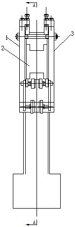
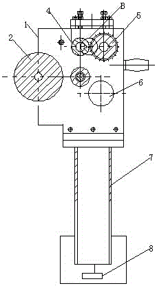
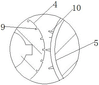
[0021] like figure 1 , figure 2 as shown in figure 1 , figure 2 , image 3 As shown, a rolling mechanism of a tread winding machine includes a first frame plate 1 and a second frame plate 3 arranged in parallel, and a main pressure roller 2 arranged between the first frame plate 1 and the second frame plate 3 , the front pressure roller 4 and the rear pressure roller 5, the front pressure roller 4 and the rear pressure roller 5 move in opposite directions to roll the film and send it to the main pressure roller 2, and the axial cross-sectional shape of the main pressure roller 2 is " H" type.

Embodiment 2

[0023] This embodiment is further improved on the basis of Embodiment 1. In this embodiment, the diameter of the front pressing roller 4 is smaller than the diameter of the rear pressing roller 5 . The rolling mechanism of the tread winding machine also includes a vertical arm 7, the upper end of the vertical arm 7 is connected to the lower end of a frame plate 1 and the second frame plate 3, and the lower end of the vertical arm 7 is connected with a driver 8, The driver 8 drives the vertical arm to move up and down. A motor 6 is further arranged between the first frame plate 1 and the second frame plate 3, and the motor 6 drives the main pressure roller 2, the front pressure roller 4 and the rear pressure roller 5 to move respectively.


PUM

PropertyMeasurementUnit
lengthaaaaaaaaaa
depthaaaaaaaaaa

Abstract

The invention provides a rolling mechanism of a tread winding machine. The rolling mechanism comprises a first frame plate and a second frame plate which are arranged in parallel as well as a main pressure roller, a front pressure roller and a rear pressure roller which are arranged between the first frame plate and the second frame plate; the front pressure wheel and the rear pressure wheel oppositely move for rolling a film and conveying the rolled film onto the main pressure roller; grooves are distributed in the front pressure roller; stab bulges which are matched with the grooves in the front pressure roller are distributed on the rear pressure roller; and the axial section of the main pressure roller is in the shape of H. The rolling mechanism of the tread winding machine is simple, is used for laminating while rubberizing and is high in laminating density, so that the quality of remanufactured tyre products is guaranteed.

Description

technical field [0001] The invention relates to the technical field of tread automatic winding rubber material in the retreading production process of engineering machinery tires, in particular to a rolling mechanism of a tread winding machine. Background technique [0002] In recent years, construction machinery tires have grown with the substantial growth in demand for loaders, forklifts, and bulldozers, and have become the fastest-growing, hottest, and most potential market in the tire market. [0003] The automatic tread winding machine is used to wind the tread rubber when retreading engineering tires. After the engineering tires are polished and enter the mold for vulcanization, raw rubber needs to be re-pasted on the polished carcass. The process is extruded by cold feed. The molding machine extrudes rubber strips with a certain thickness and width, and transports them to the winding machine through the feeding rack and conveyor belt. The operator selects the pre-edit...

Claims


Application Information

Patent Timeline
Patent Type & Authority Applications(China)
IPC IPC(8): B29D30/60
CPCB29D30/60
Inventor 徐志雄
Owner SICHUAN YUANXING RUBBER
Why Eureka
Try Eureka