Eureka AIR delivers breakthrough ideas for toughest innovation challenges, trusted by R&D personnel around the world.

A control circuit and terminal of a battery cell

A technology for controlling circuits and battery cells, applied in the field of electronics, can solve the problems of shortening the service life of batteries, aging of cells, and inability to solve the problems of mutual charging of cells, so as to prolong the service life and prevent mutual charging.

Inactive Publication Date: 2019-04-30
SHENZHEN GIONEE COMM EQUIP
View PDF2 Cites 0 Cited by
  • Summary
  • Abstract
  • Description
  • Claims
  • Application Information

AI Technical Summary

Problems solved by technology

[0003] However, the existing dual-cell or multi-cell batteries cannot solve the phenomenon of mutual charging between the cells, which is easy to cause the aging of the cells and shorten the service life of the batteries

Method used


Image

  • A control circuit and terminal of a battery cell
  • A control circuit and terminal of a battery cell
  • A control circuit and terminal of a battery cell

Examples


Embodiment 1

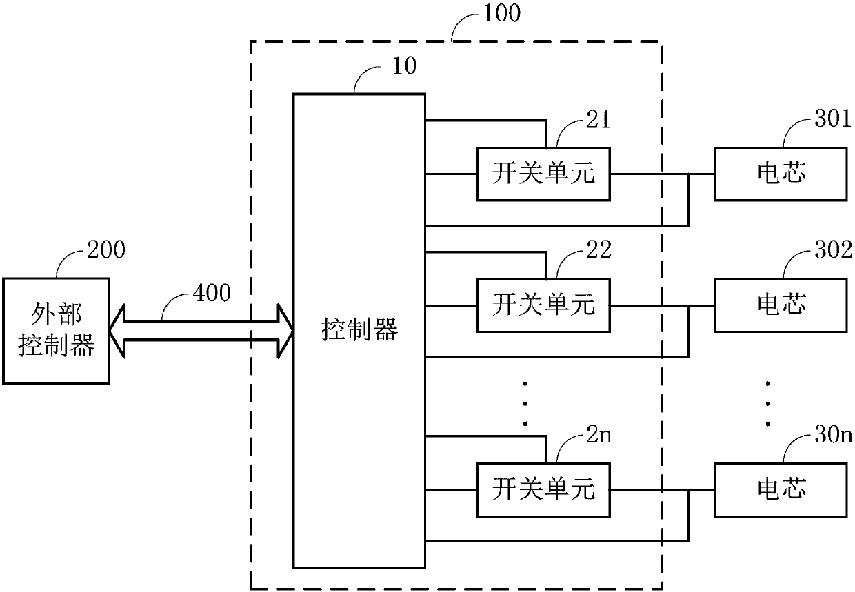
[0023] Such as figure 1 As shown, the battery cell control circuit 100 provided in this embodiment includes a controller 10 and at least two switch units 21-2n (the switch units 21-2n refer to the switch unit 21 and the switch unit 22 , ..., switch unit 2n).

[0024] The input end of the controller 10 is connected to the external controller 200 through the communication bus 400;

[0025] Each of the at least two switch units 21-2n is correspondingly connected to a cell, the controlled end of each switch unit is correspondingly connected to a control end of the controller 10, and the input of each switch unit Both terminals are connected to a switch detection terminal of the controller 10, and the output terminals of each switch unit are connected to a battery detection terminal of the controller 10 together with the input terminal of the corresponding battery cell;

[0026] If the controller 10 receives the charging notification output by the external controller 200, the con...

Embodiment 2

[0035] In this embodiment, on the basis of Embodiment 1, the switch units 21-2n are limited to MOS transistors. When the switch units 21-2n are N-type MOS transistors, the gates, sources and drains of the N-type MOS transistors respectively constitute the controlled end, input end and output end of the switch unit; when the switch units 21-2n are P-type MOS transistors, the gate, source and drain of the P-type MOS transistor respectively constitute the switch The slave, output, and input of the unit.

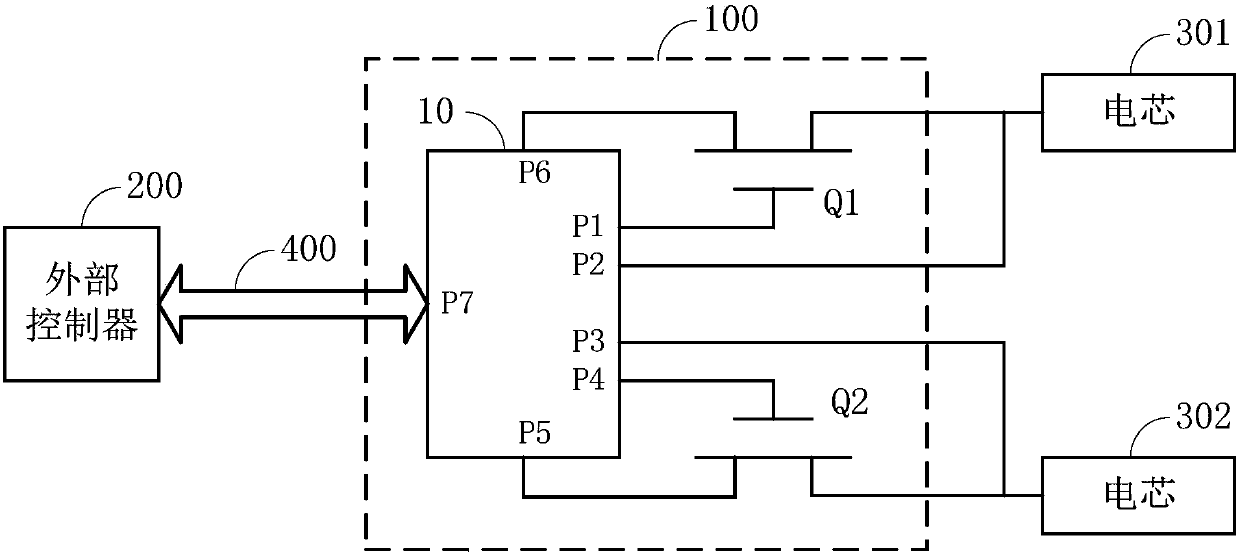
[0036] In this embodiment, the structure of the control circuit 100 is specifically described by taking the control circuit 100 including two MOS transistor switch units as an example:

[0037] Such as figure 2 As shown, the control circuit 100 includes a controller 10, a MOS transistor Q1 and a MOS transistor Q2, the MOS transistor Q1 is correspondingly connected to the battery cell 301, and the MOS transistor Q2 is correspondingly connected to the battery cell 302;

[0038]...

Embodiment 3

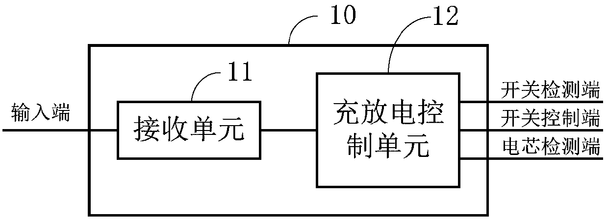
[0046] Such as image 3 As shown, this embodiment is a further refinement of the controller 10 in Embodiment 1. In this embodiment, the controller 10 includes:

[0047] a receiving unit 11, configured to receive the charging notification output by the external controller;

[0048] A charging and discharging control unit 12, configured to control at least one of the switching units to be turned on if the receiving unit 11 receives the charging notification, to charge the batteries correspondingly connected to at least one of the switching units;

[0049] The receiving unit 11 is also used to receive the discharge notification output by the external controller 200;

[0050] The charge and discharge control unit 12 is also used to control at least two switch units 21-2n to turn on sequentially if the receiving unit 11 receives the discharge notification, and when one of the switch units is turned on, the other switch units are all turned off, so that at least two At least two bat...


PUM


Abstract

Embodiments of the invention provide a control circuit for battery cells, and a terminal. The control circuit comprises a controller and at least two switch units, wherein the input end of the controller is connected with an external controller through a communication bus; each switch unit of the at least two switch units is correspondingly connected with a cell; the controlled end of each switch unit is correspondingly connected with a switch control end of the controller; the input end of each switch unit and a switch voltage detection end of the controller are jointly connected to an external power supply; and the output end of each switch unit and the input end of the corresponding cell are jointly connected to one cell voltage detection control end of the controller. By adoption of the embodiments of the control circuit for the battery cells, and the terminal, the at least two cells which are correspondingly connected with the at least two switch units are controlled through the controller to be discharged in sequence; and when one cell is discharged, other cells do not discharge, so that the mutual charging between the cells can be effectively prevented, and the service life of the cells can be prolonged.

Description

technical field [0001] The invention belongs to the field of electronic technology, and in particular relates to a control circuit and a terminal of a battery cell. Background technique [0002] With the improvement of battery life requirements for mobile terminals such as mobile phones, tablet computers, and smart bracelets, the battery capacity of mobile terminals is getting larger and larger, and dual-cell or multi-cell batteries have become an inevitable development trend. [0003] However, the existing double-cell or multi-cell batteries cannot solve the phenomenon of charging each other between the cells, which is likely to cause the aging of the cells, thereby shortening the service life of the batteries. Contents of the invention [0004] An embodiment of the present invention provides a control circuit and a terminal of a battery cell, which can effectively prevent the cells from charging each other and prolong the service life of the cells. [0005] The embodime...

Claims


Application Information

Patent Timeline
Patent Type & Authority Patents(China)
IPC IPC(8): H02J7/00
CPCH02J7/0068
Inventor 江克俊刘海强曹晓杰
Owner SHENZHEN GIONEE COMM EQUIP
Why Eureka
Eureka Blog
Learn More