Transformer fault cumulative effect evaluation method based on topological model of power distribution network

A distribution network topology and transformer fault technology, applied in the direction of electrical components, circuit devices, AC network circuits, etc., can solve the problems of complex modeling of distribution network topology, huge amount of calculation data, unfavorable rapid evaluation, etc., and achieve good results Application prospects, rapid evaluation, and the effect of fast calculation cycles

Active Publication Date: 2016-11-16
STATE GRID JIANGSU ELECTRIC POWER CO ELECTRIC POWER RES INST +3
View PDF4 Cites 7 Cited by
  • Summary
  • Abstract
  • Description
  • Claims
  • Application Information

AI Technical Summary

Problems solved by technology

[0004] The purpose of the present invention is to overcome the large number of outgoing lines in the distribution network in the prior art, and its structure is mostly tree-type and ring-type. The topology modeling of the distribution network is very complicated, the amount of calculation data is huge, and the power distribution network is not used. Problems of Rapid Assessment for Assessment of Cumulative Effects of Network Transformer Equipment Faults

Method used


Image

  • Transformer fault cumulative effect evaluation method based on topological model of power distribution network
  • Transformer fault cumulative effect evaluation method based on topological model of power distribution network
  • Transformer fault cumulative effect evaluation method based on topological model of power distribution network

Examples


Embodiment Construction

[0027] The present invention will be further described below in conjunction with the accompanying drawings.

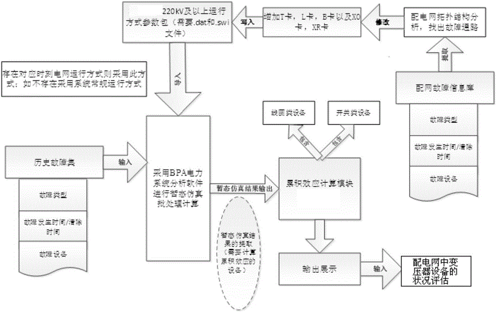
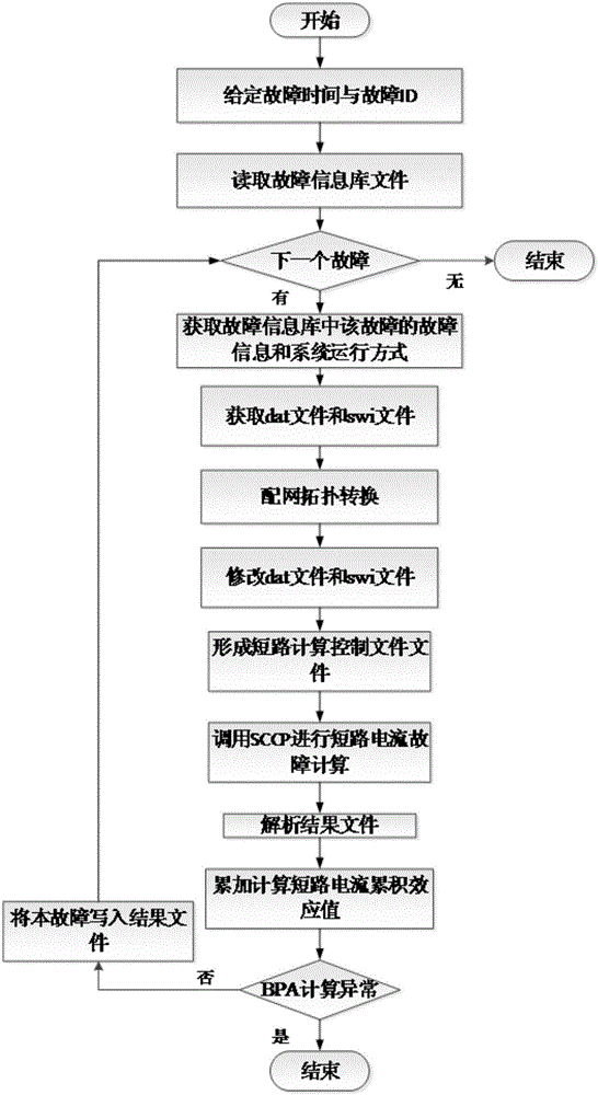
[0028] The method for evaluating the accumulative effect of transformer faults based on the distribution network topology model of the present invention, such as figure 1 shown, including the following steps,

[0029] Step (A), through the fault extraction module, extract the necessary fault information from the fault information database, the necessary fault information includes fault ID, fault time, city ID, fault type, substation ID, substation name, substation voltage level and reclosing In this case, use the Dictionary function in C# to store and read fault information, obtain the main network operation mode file (PSD-BPA format, *.dat) and transient stability parameter file (PSD-BPA, *. swi);

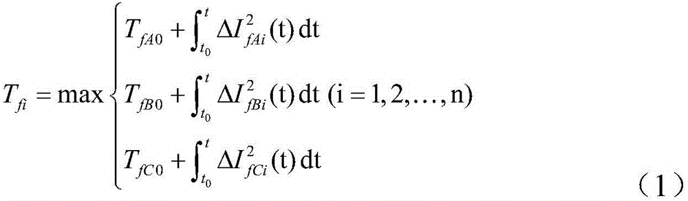
[0030] Step (B), through the distribution network topology conversion module, build a distribution network topology model, complete the calculation of the distribution n...


PUM


Abstract

The invention discloses a transformer fault cumulative effect evaluation method based on a topological model of a power distribution network. The transformer fault cumulative effect evaluation method comprises the following steps of: depending on batch processing of a transient simulation program and a short-circuit current calculation program of simulation software PSD-BPA, completing a transformer cumulative effect evaluation function of the power distribution network by setting up a topological model of the power distribution network, calculating electric parameters and operation modes of the topological model of the power distribution network and the practical power distribution network, modifying the operation mode of a main network and a transient steady file, and setting up an end bus short-circuit fault simulation model of the power distribution network and a short-circuit calculation method; and, after the end bus of the power distribution network is failed, calculating short-circuit current flowing through a transformer via a transformer short-circuit fault current cumulative effect calculation model, superposing the short-circuit current with a cumulative effect initial value so as to obtain a transformer short-circuit fault current cumulative effect value, finally, outputting a result to perform graphical display, and performing evaluation. By means of the transformer fault cumulative effect evaluation method disclosed by the invention, condition early-warning and equipment overhaul preference strategies are provided for power distribution network equipment; and thus, the transformer fault cumulative effect evaluation method has good application prospects.

Description

technical field [0001] The invention relates to the technical field of electric power automation, in particular to a transformer fault accumulation effect evaluation method based on a distribution network topology model. Background technique [0002] The evaluation of cumulative effect of transformer equipment failure in distribution network refers to the evaluation of the cumulative effect of the through-circuit short-circuit current flowing on transformer equipment and the impact of overload current on equipment when short-circuit faults or overcurrents occur repeatedly in the distribution network for a long time. The calculation method is to traverse all the fault paths based on recursive operation, and complete the establishment of distribution network topology model and topology conversion; based on the historical fault data of distribution network, a batch calculation model of short-circuit current and overload current is established, Calculate its impact on the assess...

Claims


Application Information

Patent Timeline
Patent Type & Authority Applications(China)
IPC IPC(8): H04L12/24H02J3/00H02J13/00
CPCH02J3/00H02J13/0086H02J2203/20H04L41/06H04L41/12H04L41/145
Inventor 杨毅高磊袁宇波曹军龚雁峰王海啸李斌宋爽林金娇
Owner STATE GRID JIANGSU ELECTRIC POWER CO ELECTRIC POWER RES INST
Why Eureka
Try Eureka