Pivoting Variable Cam Follower

一种凸轮随动件、可变的技术,应用在凸轮随动件、凸轮、发动机元件等方向,能够解决挺杆/凸轮接触系统没有经历实施方案或成功、缺乏成功等问题

Inactive Publication Date: 2016-11-16
丹尼尔·波默洛
View PDF10 Cites 7 Cited by
  • Summary
  • Abstract
  • Description
  • Claims
  • Application Information

AI Technical Summary

Problems solved by technology

[0020] While variable valve timing systems have been disclosed in the past, for example in US Patent 2969051, German Publication DE 197 55 937, Swiss Publication DE 304494 and US Patent 2307926 and PCT Publication No.W002 / 12682, tappet / cam contact systems have not. experience widespread implementation or success
The reason for this lack of success is that the assumption is the result of failures experienced in practical implementations of such systems

Method used


Image

  • Pivoting Variable Cam Follower
  • Pivoting Variable Cam Follower
  • Pivoting Variable Cam Follower

Examples


Embodiment Construction

[0062] Fundamental

[0063] Axial displacement of the camshaft has been accomplished by pushing against a clutch-like bearing assembly using hydraulic pistons or mechanical actuators. The actuation may be provided automatically with respect to the change in rotational speed or linked to the throttle position. It will be appreciated that springs may be used to restore and resist valve movement. Airbags, hydraulic systems and track systems can replace springs for this type of variable valve technology. Variations in valve timing during engine operation allow engine performance to be modified to match operating conditions. Variations in the relative shape of a given cam within a variable cam system may enable independent phasing of the intake cams, independent phasing of the exhaust cams, equal phasing of the intake and exhaust, or phasing of the exhaust and exhaust cams. The intake cams are phased independently of each other.

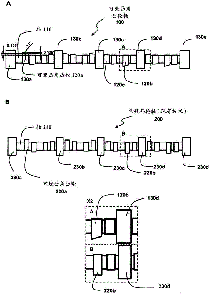
[0064] In previous efforts to produce improved ...


PUM


Abstract

A cam follower for operable attachment to a valve lifter assembly for use with a variable cam lobe camshaft in a variable valve timing system includes a housing with a central cavity and a mushroom head with a stem pivotably connected to the housing in the central cavity, the mushroom head having a radiused surface for contacting a cam lobe surface. The cam follower is used in combination with a variable cam surface of an axially displaceable camshaft to obtain improvements in idling speed and volumetric efficiency.

Description

technical field [0001] The present invention relates to an improved cam contact arrangement for use in internal combustion engines and preferably for use in internal combustion engines with variable valve actuation. In particular, a cam follower with a pivoting mushroom head cam follower is used in combination with a variable cam surface of an axially displaceable camshaft to obtain improvements in idle speed and volumetric efficiency. Background technique [0002] The design of an internal combustion engine requires numerous trade-offs between conflicting design or performance parameters, especially with respect to camshaft design and thus with respect to valve actuation. [0003] For example, in the design of an engine, a designer may want to minimize exhaust emissions and provide improved fuel economy without compromising satisfactory engine performance. In the past, the design of such an engine would be constrained by such conflicting parameters, leading designers to co...

Claims


Application Information

Patent Timeline
Patent Type & Authority Applications(China)
IPC IPC(8): F01L1/34F01L1/18F01L1/344F16C3/28F16H53/04F16H53/06
CPCF16H53/06F01L1/08F01L1/146F01L1/181F01L13/0042F01L2810/02F01L2820/01F01L2001/0476F01L1/14F01L3/22F01L2013/0078F01L2305/00F01L1/16F01L1/0532F01L1/34416F01L2003/11F01L1/18F01L13/0047
Inventor 丹尼尔·波默洛
Owner 丹尼尔·波默洛
Why Eureka
Try Eureka