Vacuum management system for engine with variable valve lift

a technology of valve lift and management system, which is applied in the direction of machines/engines, non-mechanical valves, combustion air/fuel air treatment, etc., can solve the problems of consuming valuable onboard space, no useful level of manifold vacuum, and adding cost to vehicles, so as to improve fuel economy

Inactive Publication Date: 2005-03-15
DELPHI TECH INC
View PDF7 Cites 36 Cited by
  • Summary
  • Abstract
  • Description
  • Claims
  • Application Information

AI Technical Summary

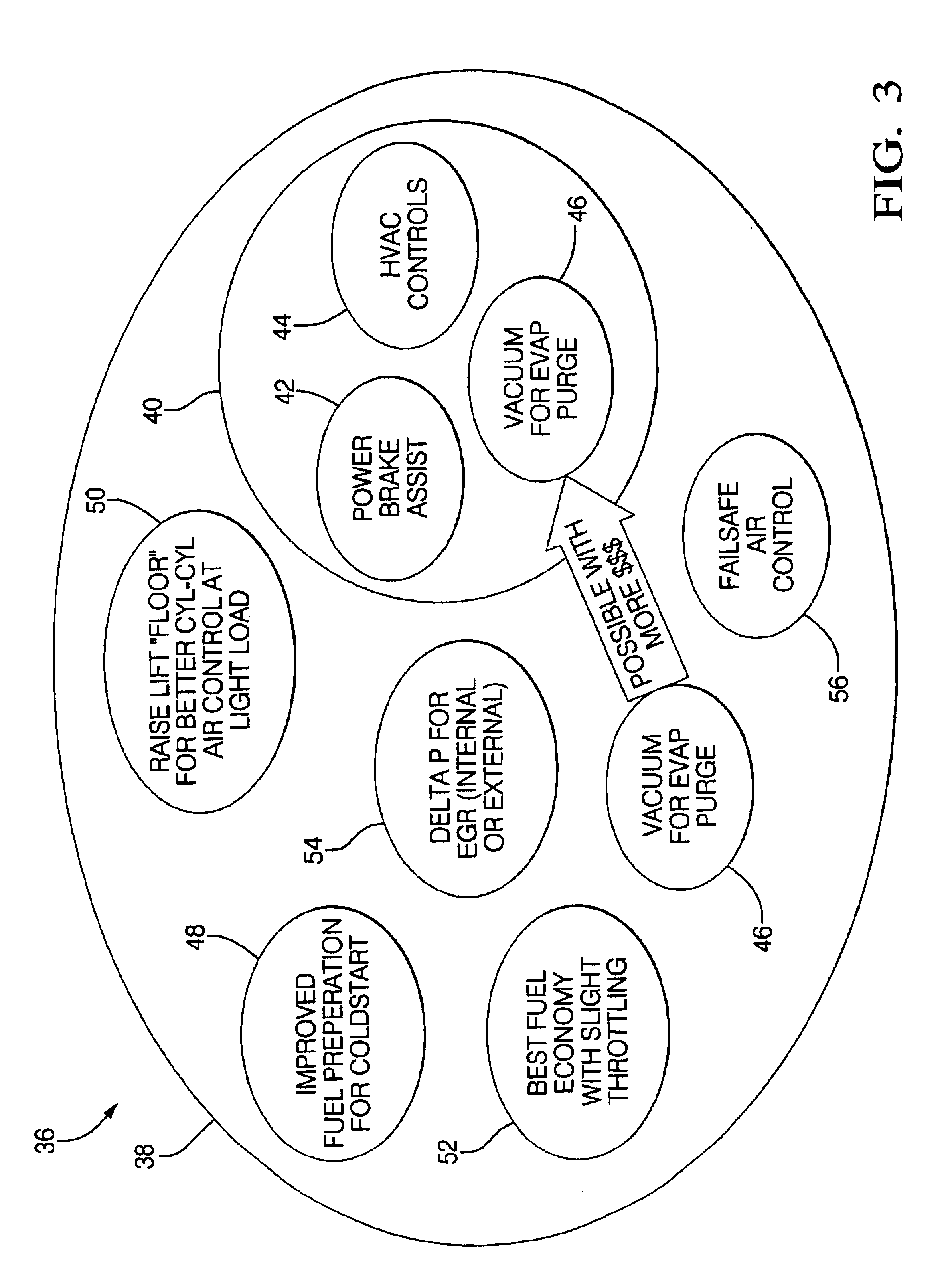
Benefits of technology

to provide such a system w...

Problems solved by technology

A first unfavorable consequence of eliminating a manifold throttle valve is that the air pressure within the manifold is substantially the same as atmospheric pressure outside the engine; i.e., there is no useful level of manifold vacuum.
Providing an auxiliary vacuum pump for auxiliary automotive devices adds cost to a vehicle, consumes valuable onboard space, and parasitically decreases fuel economy.
Engine functions, such ...

Method used


Image

  • Vacuum management system for engine with variable valve lift
  • Vacuum management system for engine with variable valve lift
  • Vacuum management system for engine with variable valve lift

Examples


Embodiment Construction

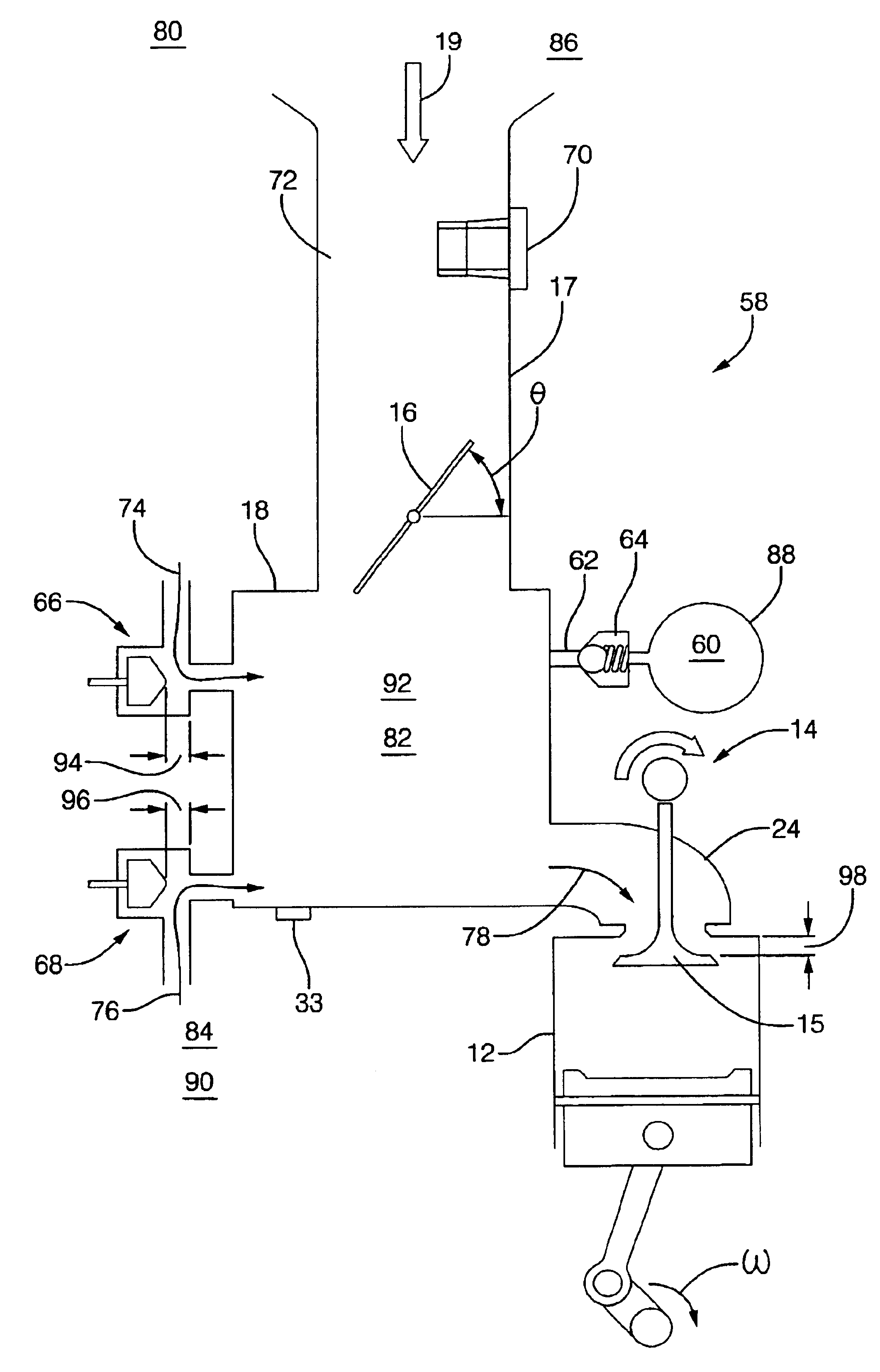
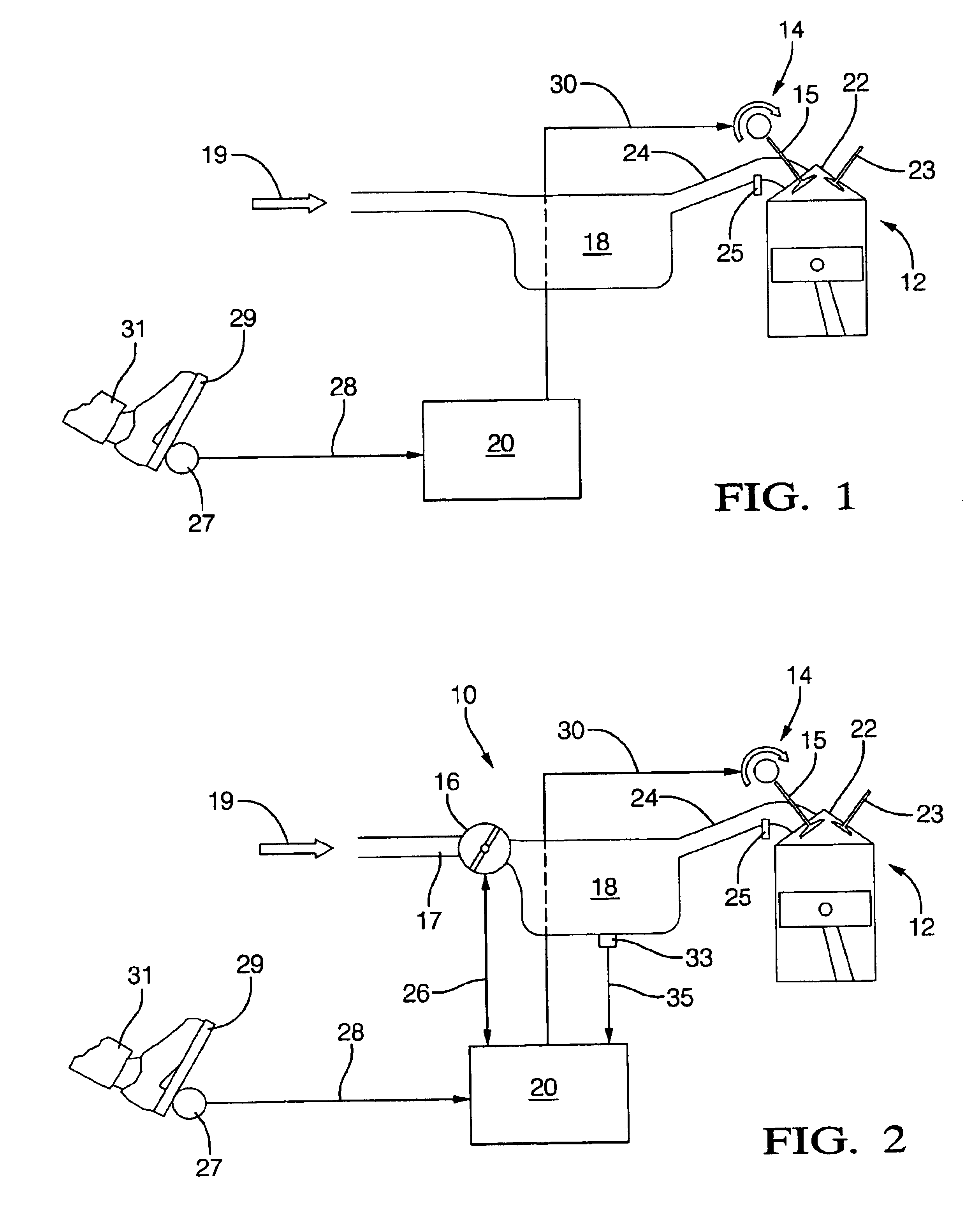
Referring to FIG. 1, a fuel-injected engine 12 with variable valve lift (VVL) means 14 for actuation of intake valve 15 includes a programmable engine control module 20 (ECM). (It should be understood that engine 12 is a multiple-cylinder engine and that valve 15 is individually representative of a plurality of engine valves in a plurality of engine cylinders.) Intake manifold 18 is connected for air flow 19 to engine head 22 via runner 24 which supports a conventional fuel injector 25. Head 22 supports intake valve 15 and exhaust valve 23. The ECM is electrically connected to VVL lift means 14 via first lead 30 for varying the lift of intake valve 15. Engine throttling and consequent torque control is provided by varying the lift of the intake valves via ECM 20 in response to engine load request from an electronic pedal module 27 connected via second lead 28 and responsive to positional input of accelerator pedal 29 from operator 31. ECM 20 may be further connected to other engine ...


PUM


Abstract

A vacuum management system for an engine with variable valve lift includes a vacuum control valve at the entrance to the intake manifold to increase vacuum within the manifold as needed and preferably only when it can be done without impairing fuel economy or engine performance. Vacuum may then be used for any of various vacuum-assisted devices and functions, for example, boosting a vehicle braking system. The numerical relationships among important operating parameters are determined in a laboratory, and a programmable engine control module (ECM} is provided with algorithms and tables of such values by which the ECM is able to vary valve lift and vacuum control valve position to provide optimum flow across the intake valves and optimum manifold vacuum under all engine operating conditions.

Description

TECHNICAL FIELDThe present invention relates to internal combustion engines; more particularly, to such engines wherein devices for variably controlling the lift of intake valves are the primary throttling means of the engine; and most particularly, to a system for providing and managing manifold vacuum in such an engine to optimize fuel economy and enable vacuum-assisted devices such as a brake booster.BACKGROUND OF THE INVENTIONFuel-injected internal combustion engines are well known, especially for automotive applications. Torque output of such an engine is typically controlled by moderating airflow into the engine via a throttle device. The throttle, usually a butterfly valve disposed at the entrance to the engine intake manifold, may be directly actuated by a driver's foot pedal or may be electronically governed through a digital or analog controller. Under typical driving conditions, the engine is substantially throttled. Because the engine is a positive displacement pump, a v...

Claims


Application Information

Patent Timeline
IPC IPC(8): F02D13/02F02D9/08
CPCF02D9/08F02D13/02Y02T10/18F02D2013/0296Y02T10/12
Inventor ALLSTON, BRIAN K.BURKHARD, JAMES F.
Owner DELPHI TECH INC
Why Eureka
Try Eureka