Hybrid vehicle powertrain with a multiple-ratio power transmission mechanism

Active Publication Date: 2005-03-10
FORD GLOBAL TECH LLC
View PDF7 Cites 85 Cited by
  • Summary
  • Abstract
  • Description
  • Claims
  • Application Information

AI Technical Summary

Benefits of technology

[0010] The invention includes a strategy for controlling power-on upshifts and coasting, reduced-throttle downshifts in a multiple-ratio transmission for a converterless powertrain of the kind described in the preceding background discussion. The strategy uses a starter/alternator, sometimes referred to herein a

Problems solved by technology

This results in torque modulation of shift events by r

Method used


Image

  • Hybrid vehicle powertrain with a multiple-ratio power transmission mechanism
  • Hybrid vehicle powertrain with a multiple-ratio power transmission mechanism
  • Hybrid vehicle powertrain with a multiple-ratio power transmission mechanism

Examples


Example

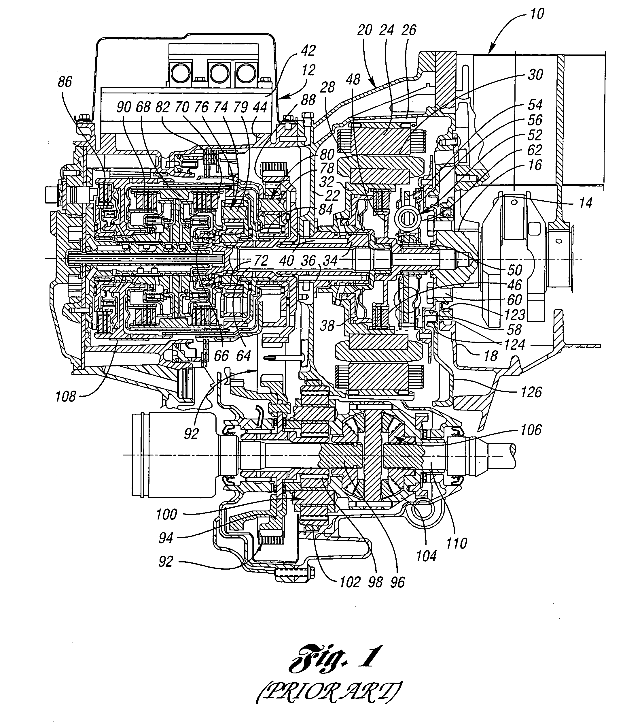
[0050] In FIG. 1, reference numeral 10 designates schematically an internal combustion engine for an automotive vehicle. Numeral 12 designates generally a multiple-ratio automatic transmission.

[0051] The engine 10 includes a crankshaft 14 journalled at 16 in end wall 18 of the engine housing. An intermediate housing 20 is located between the end wall 18 of the engine 10 and wall 22 for the transmission 12.

[0052] The intermediate housing encloses a stator 24 of an electric motor. The stator and the stator windings are secured to an interior machined surface 26 of the housing 20. A rotor assembly 28 is situated within the stator and separated from the stator by an air gap designated by numeral 30.

[0053] A wet clutch cylinder 32 is secured to the rotor assembly 28. A support bearing shaft 34 rotatably supports the clutch cylinder 32 and is secured by bolts 36, or by other suitable fastening techniques, to the transmission wall 22.

[0054] An annular piston 38 situated within the clut...


PUM


Abstract

A control method and system for a hybrid vehicle powertrain with an electric motor in a power flow path between an internal combustion engine and a multiple-ratio geared transmission. Motor torque, which is added to engine torque to obtain an effective transmission input torque, is modulated to achieve smooth power-on upshifts and coasting downshifts.

Description

CROSS-REFERENCE TO RELATED APPLICATIONS [0001] This application claims the benefit of U.S. provisional application Ser. No. 60 / 501,706, filed Sep. 10, 2003.BACKGROUND OF THE INVENTION [0002] 1. Field of the Invention [0003] The invention relates to hybrid vehicle powertrains with an internal combustion engine, a multiple-ratio transmission and an electric starter / alternator motor between the engine and the transmission. [0004] 2. Background Art [0005] A contemporary automotive vehicle powertrain typically includes a hydrokinetic torque converter disposed between a transmission with multiple-ratio gearing and an internal combustion engine. The turbine of the torque converter transfers power to the power input element of the multiple-ratio gearing. [0006] The presence of the torque converter in a vehicle powertrain of this type introduces hydrokinetic power losses, particularly during vehicle start up and advanced throttle downshifts. The power losses are manifested by thermal energy ...

Claims


Application Information

Patent Timeline
IPC IPC(8): B60K6/365B60K6/48B60W10/06B60W10/08B60W10/10B60W20/00F16H61/04
CPCB60K6/365Y10T477/32B60L2240/423B60L2240/441B60L2240/443B60L2240/486B60W10/06B60W10/08B60W10/10B60W20/00B60W2510/0638B60W2510/0657B60W2540/10B60W2540/16B60W2710/083F16H61/0437F16H61/686F16H63/502F16H2306/42Y02T10/6221Y02T10/6286Y02T10/642Y10T477/26Y10T477/33Y10T477/27Y10T477/322B60K6/48Y02T10/62Y02T10/64B60K2006/268B60W20/30
Inventor ORTMANN, WALTCOLVIN, DANFOZO, BOBENCELEWSKI, MICHAELKRASKA, MARVIN
Owner FORD GLOBAL TECH LLC
Why Eureka
Try Eureka