

Turbo charging in a variable displacement engine
- Summary
- Abstract
- Description
- Claims
- Application Information
AI Technical Summary
Benefits of technology
Problems solved by technology
Method used
Image

Examples
Embodiment Construction
)
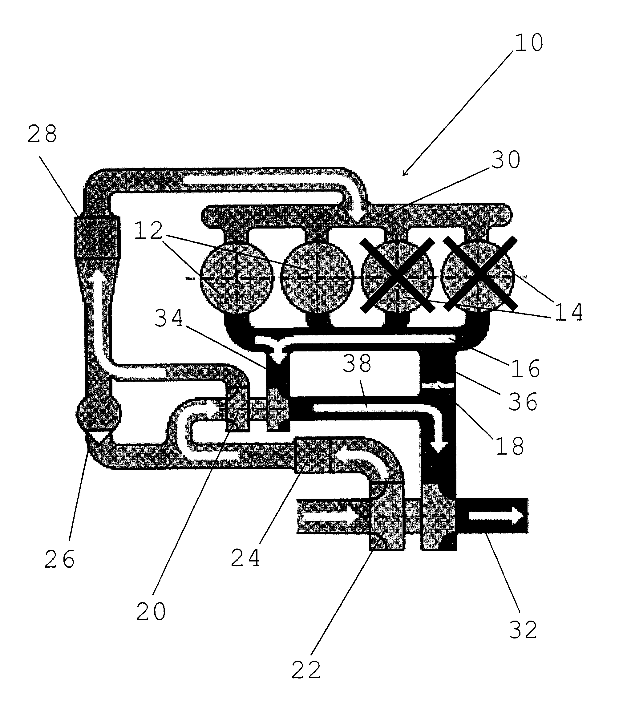
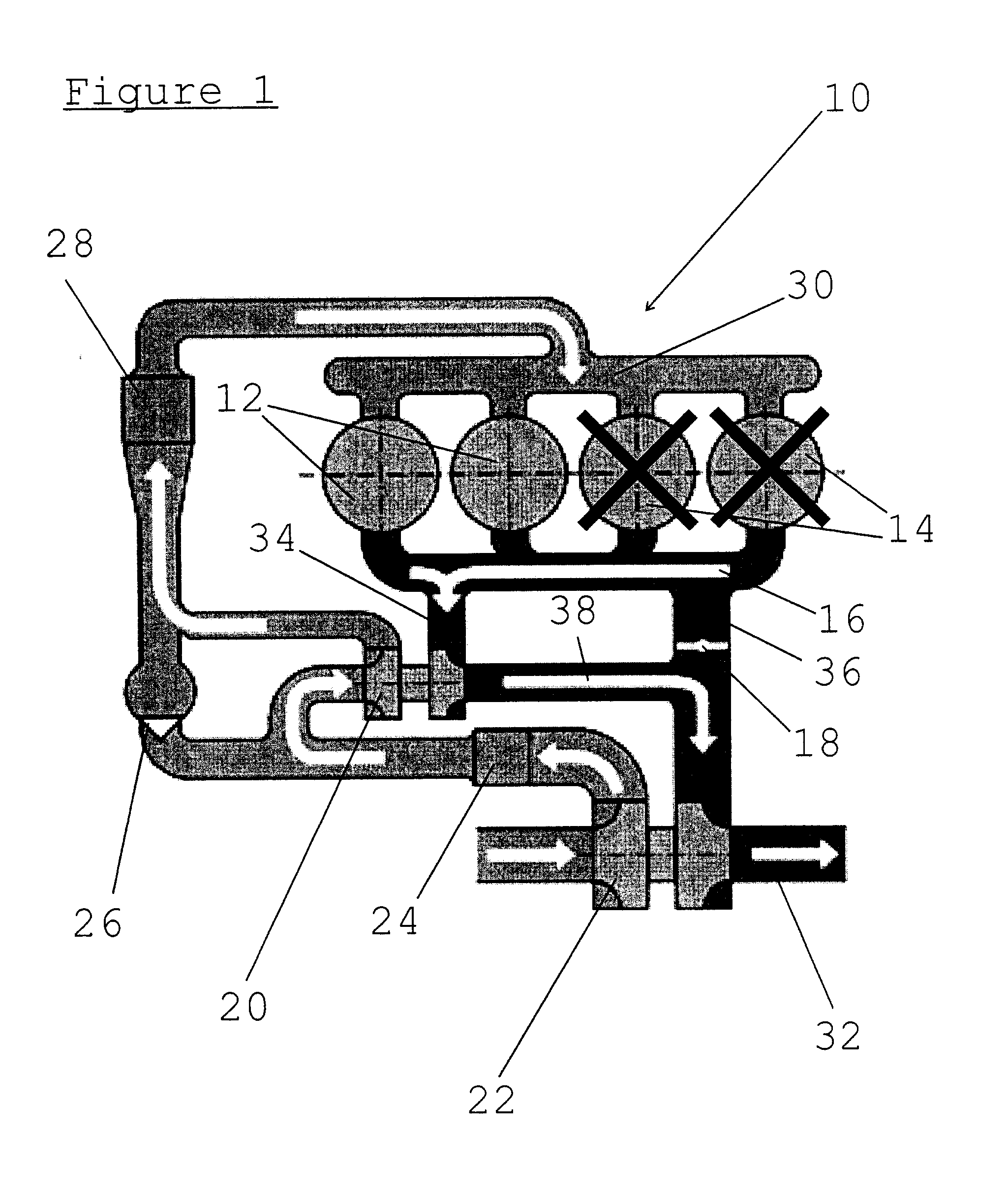
[0015]FIG. 1 shows a variable displacement engine 10 operating in a reduced displacement operating mode. In this mode two of the four cylinders remain active 12, whilst two others, designated 14, are disabled. When disabled the inlet and exhaust valves to the cylinder remain closed and make no contribution to the exhaust gases.
[0016] When operating with only two cylinders, the engine is more efficient, and thus is it preferable to run in this mode whenever possible.
[0017] In conventional turbo diesel engines, exhaust gases power the turbocharger, which compresses the air entering the cylinders. The more air and fuel that can be burned in the cylinder, the more power the engine can produce. However, when employing variable displacement technology, the exhaust gases from (in this example) only two cylinders is insufficient to operate the turbocharger in its useful s efficiency range as its size would normally have been chosen for use with all the engine's available cylinders.
[0018...
PUM
 Abstract
Description
Claims
Application Information