Drip irrigation device
A kind of equipment and technology of drip irrigation head, which is applied to drip irrigation water for fruits and vegetables in greenhouses, and supplies water to the garden field.
Inactive Publication Date: 2016-11-23
刘清海
View PDF0 Cites 2 Cited by
- Summary
- Abstract
- Description
- Claims
- Application Information
AI Technical Summary
Problems solved by technology
[0003] The present invention aims at the problem of flood irrigation of crops in existing greenhouses, and specially designs a drip tank equipment. In this technical room, a plurality of water filter screens are arranged in the inner cavity of each drip irrigation head, and the sundries in the water are filtered out from the filter. After the net flows out, it can flow to the drip irrigation head and then flow to the drip-irrigated crops
Method used
View moreImage
Smart ImageViewing Examples

Examples
Embodiment Construction
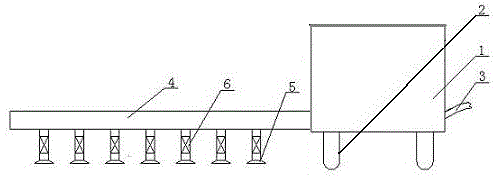
[0008] A drip irrigation vehicle as shown in the figure, including the ground wheel (2) device at the bottom of the water tank (1) for easy moving, the water inlet pipe (3) is fastened on the water tank (1) to facilitate the installation of the water tank (1) Water, the inner cavity of a plurality of drip irrigation heads (5) is equipped with filter screens (6) respectively fastened on the same water pipes (4).
Login to View More PUM
 Abstract
The invention provides a drip irrigation device for planting of dry farming. The drip irrigation device comprises a vehicle body and a support. The support is provided with a plurality of drip irrigation heads sharing a water supply pipeline to supply water. An inner cavity of each drip irrigation head is provided with a plurality of water filtering nets, impurities in water flow out of the filter nets, then, water flows to the drip irrigation heads and crops to be subjected to drip irrigation. The number of the on drip irrigation heads can be adjusted according to the planting density of the crops. Meanwhile, adjusting rods are arranged between the vehicle body and the support of the drip irrigation device, and the spraying height can be adjusted according to the heights of the crops. The drip irrigation device is convenient to use, low in machining expenditure, small in water consumption and suitable for large-area use and popularization.
Description
technical field [0001] The invention relates to a drip tank device for dry farming, in particular for drip irrigation of melons, fruits and vegetables in courtyards and greenhouses. Background technique [0002] The existing greenhouses are generally equipped with water supply pipes. When the crops need to be watered, the valve on the water supply pipe is opened to put the water into the farmland. This traditional watering method consumes a lot of water. In agricultural planting areas where water resources are scarce Obviously not applicable. In order to solve the above problems, people invented the drip irrigation technology, but the laying cost of the drip irrigation belt is high and the service life is short. In addition, the position of the drip irrigation belt must be readjusted every year according to the position of the new plant. Contents of the invention [0003] The present invention aims at the problem of flood irrigation of crops in existing greenhouses, and s...
Claims
Login to View More Application Information
Patent Timeline
 IPC IPC(8): A01G25/09
CPCY02A40/22
Inventor 刘清海
Owner 刘清海
Features
- R&D
- Intellectual Property
- Life Sciences
- Materials
- Tech Scout
- Unparalleled Data Quality
- Higher Quality Content
- 60% Fewer Hallucinations
Learn More Browse by: Latest US Patents, China's latest patents, Technical Efficacy Thesaurus, Application Domain, Technology Topic, Popular Technical Reports.
© 2025 PatSnap. All rights reserved.Legal|Privacy policy|Modern Slavery Act Transparency Statement|Sitemap|About US| Contact US: help@patsnap.com