Forging die

A die and die holder technology, which is applied in the manufacture of tools, forging/pressing/hammer devices, and forging/pressing/hammering machines, etc., can solve the problems of unbalanced force and low installation accuracy.

Inactive Publication Date: 2016-11-23
CHANGLI FORGING
View PDF6 Cites 14 Cited by
  • Summary
  • Abstract
  • Description
  • Claims
  • Application Information

AI Technical Summary

Problems solved by technology

[0003] The purpose of the present invention is to overcome the low installation precision and error of the existing forging die. Once the error occurs between the upper and lower dies, it will inevitably cause the defect of unbalanced force when the die is closed. A forging die is des

Method used


Image

  • Forging die
  • Forging die
  • Forging die

Examples


Embodiment Construction

[0022] In order to make the technical means, creative features, goals and effects achieved by the present invention easy to understand, the present invention will be further described below in conjunction with specific illustrations.

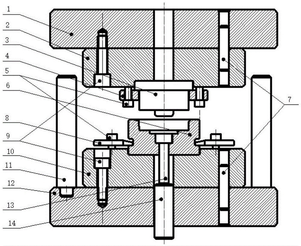
[0023] A forging die, comprising an upper die seat backing plate 1, an upper die seat 2, an upper die 3, a flange pressing plate 4, an inner hexagon screw 5, a lower die 6, a pin 7, a pressing plate 8, a bolt 9, a lower die seat 10, The support rod 11, the backing plate 12 of the lower die base, the ejector rod 13, the lower ejector rod 14, the base plate 1 of the upper die base and the upper die base 2 are first inserted into the holes of the two by the pin 7 for positioning, and then fixedly connected by bolts 9, The upper mold 3 is pressed on the upper mold base 2 by the flange plate 4 through the hexagon socket head cap screw 5, and the lower mold base backing plate 12 and the lower mold base 10 are also firstly inserted into the holes of the...


PUM


Abstract

The invention discloses a forging die, which belongs to the technical field of die design, and includes an upper die seat backing plate, an upper die seat, an upper die, a flange pressing plate, an inner hexagon screw, a lower die, pins, a pressing plate, bolts, and a lower die Seat, support rod, lower mold base plate, ejector rod, lower ejector rod, upper and lower mold base plate and upper and lower mold bases are first inserted into the holes of the two for positioning by pins, and then fixed and connected by bolts. The flange pressing plate is pressed on the upper mold base through the hexagon socket head screw, the support rod is fixed on the upper surface of the lower mold base backing plate, and a through hole is drilled in the middle of the lower mold base backing plate, and the lower ejector rod is installed in this hole. The upper part of the ejector pin is located in the middle hole of the lower mold base and the lower mold. The forging die disclosed by the present invention has a high position accuracy between the upper and lower mold bases and the backing plates of the upper and lower mold bases. Both the upper mold and the lower mold are Reliable fixation, easy installation and disassembly of support rods, relatively balanced force when closing molds.

Description

technical field [0001] The invention relates to the technical field of die design, in particular to a forging die. Background technique [0002] In the past, most of the production dies for forgings were simple upper dies and lower dies, which were directly installed on the forging bed. Errors between the molds will inevitably cause unbalanced force during mold closing, and waste products are likely to be produced. Therefore, a design with high position accuracy between the upper and lower mold bases and the upper and lower mold base plates, and the upper and lower molds are fixed and reliable , the support rod is easy to install and disassemble, and the forging mold with relatively balanced force when closing the mold is very necessary. Contents of the invention [0003] The purpose of the present invention is to overcome the low installation precision and error of the existing forging die. Once the error occurs between the upper and lower dies, it will inevitably cause ...

Claims


Application Information

Patent Timeline
IPC IPC(8): B21J13/02
Inventor 杨奎琦
Owner CHANGLI FORGING
Why Eureka
Try Eureka