A Split Labyrinth Magnetic Fluid Sealing Device

A magnetic fluid sealing and splitting technology, applied in the direction of engine sealing, engine components, mechanical equipment, etc., can solve the problems of not allowing disassembly, time-consuming, low sealing pressure resistance, etc., to expand the safety work. range, overcoming the effect of low sealing performance and reliable sealing performance

Active Publication Date: 2018-04-06
GUANGXI UNIVERSITY OF TECHNOLOGY
View PDF9 Cites 1 Cited by
  • Summary
  • Abstract
  • Description
  • Claims
  • Application Information

AI Technical Summary

Problems solved by technology

[0002] The magnetic fluid seal has the advantages of zero leakage, long life, high reliability, etc. It has been widely used in all walks of life, but the traditional magnetic fluid sealing device is an integral structure. In the process of assembling the sealing device, it is necessary to first Install the shaft end into the sealing device, and then connect the shaft end of the equipment with complex equipment. When the shaft end of the rotating shaft where the magnetic fluid seal is located is connected to complex equipment, inconvenient to assemble and disassemble or even not allowed to disassemble, not only the assembly process requires It takes a lot of time, the assembly effect is affected, and it is difficult to replace the corresponding sealing parts when the seal fails
In view of this defect, the use of split-type sealing structure makes it possible for the magnetic fluid sealing device to be used in complex equipment, and it is easy to maintain and replace. However, the existing split-type magnetic fluid sealing device has the problem of low sealing pressure resistance. It makes it difficult to use the split-type sealing device under high pressure and other working conditions

Method used


Image

  • A Split Labyrinth Magnetic Fluid Sealing Device
  • A Split Labyrinth Magnetic Fluid Sealing Device

Examples


Embodiment Construction

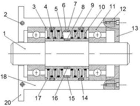
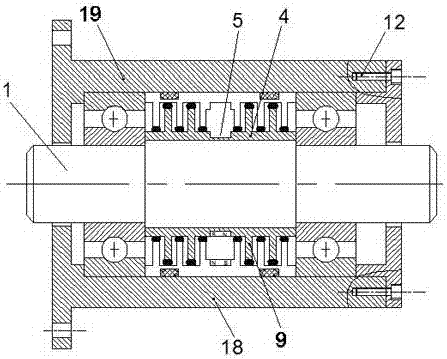
[0022] The present invention will be further described below in conjunction with the accompanying drawings.

[0023] Such as Figure 1-2 A split-type labyrinth-type ferrofluid sealing device shown includes a shaft 1, a housing, an inner pole shoe ring 4, a split-type outer pole shoe, a split-type inner permanent magnet, and a split-type outer permanent magnet. The shaft 1 is installed in the shell, the outer circle of the shaft 1 is the same as the axis of the inner circle of the shell, the inner pole shoe ring 4 is set on the shaft 1, and the outer circle of the inner pole shoe ring 4 is A concave annular groove I5 is provided in the middle of the surface, and the outer circular surface of the inner pole shoe ring 4 is divided into a left half surface I and a right half surface I by the said annular groove I5, and the said left half surface I and the right half surface I are respectively More than two sets of annular pole teeth I9 are set at intervals;

[0024] The split-ty...


PUM


Abstract

The invention relates to the technical field of mechanical engineering sealing, and specifically relates to a split labyrinth type magnetofluid sealing device. The device comprises an internal pole shoe ring, a split external pole shoe, a split internal permanent magnet and a split external permanent magnet, wherein the internal pole shoe ring is of an integrally-formed structure, annular grooves are arranged in the middle parts of the outer wall of the internal pole shoe ring and the inner wall of the split external pole shoe, and the permanent magnets are installed in the annular grooves; and pole teeth I are arranged on the outer wall of the internal pole shoe ring, pole teeth II are arranged on the inner wall of the split external pole shoe, the pole teeth I are enabled to stretch in spaces among the pole teeth II on the split external pole shoe, and the pole teeth II are enabled to stretch in spaces at the two sides of the pole teeth I on the internal pole shoe ring, so as to form a labyrinth type sealing structure. The sealing structure is high in pressure-resistant capacity and reliable in sealing performance.

Description

technical field [0001] The invention relates to the technical field of mechanical engineering sealing, in particular to a split labyrinth magnetic fluid sealing device with good sealing performance. Background technique [0002] The magnetic fluid seal has the advantages of zero leakage, long life, high reliability, etc. It has been widely used in all walks of life, but the traditional magnetic fluid sealing device is an integral structure. In the process of assembling the sealing device, it is necessary to first Install the shaft end into the sealing device, and then connect the shaft end of the equipment with complex equipment. When the shaft end of the rotating shaft where the magnetic fluid seal is located is connected to complex equipment, inconvenient to assemble and disassemble or even not allowed to disassemble, not only the assembly process requires It takes a lot of time, the assembly effect is affected, and it is difficult to replace the corresponding sealing part...

Claims


Application Information

Patent Timeline
Patent Type & Authority Patents(China)
IPC IPC(8): F16J15/43
CPCF16J15/43
Inventor 杨小龙孙康康
Owner GUANGXI UNIVERSITY OF TECHNOLOGY
Why Eureka
Try Eureka