Flat gate valve with valve plate position indication function

A technology for flat gate valves and valve plates, which is applied in the direction of valve devices, sliding valves, engine components, etc., and can solve the problems of inaccurate judgment of the operating position of the valve plate, insufficient sealing between the valve seat and the valve body, and inability to control fluid flow, etc. , to achieve the effect of convenient implementation, simple structure and low cost

Active Publication Date: 2016-11-23
US DIAMOND OIL DRILLING SYST ENG (SHANGHAI) CO LTD
View PDF6 Cites 5 Cited by
  • Summary
  • Abstract
  • Description
  • Claims
  • Application Information

AI Technical Summary

Problems solved by technology

[0004] However, in actual operation, the valve seat not only needs to limit the rotation of the valve plate, but also needs to rub against the valve plate for a long time, which will easily cause insufficient sealing between the valve seat and the valve body, resulting in leakage accidents
[0005] At the same time, the running position of the valve plate cannot be accurately judged, so the flow of the fluid cannot be controlled.

Method used


Image

  • Flat gate valve with valve plate position indication function

Examples


Embodiment Construction

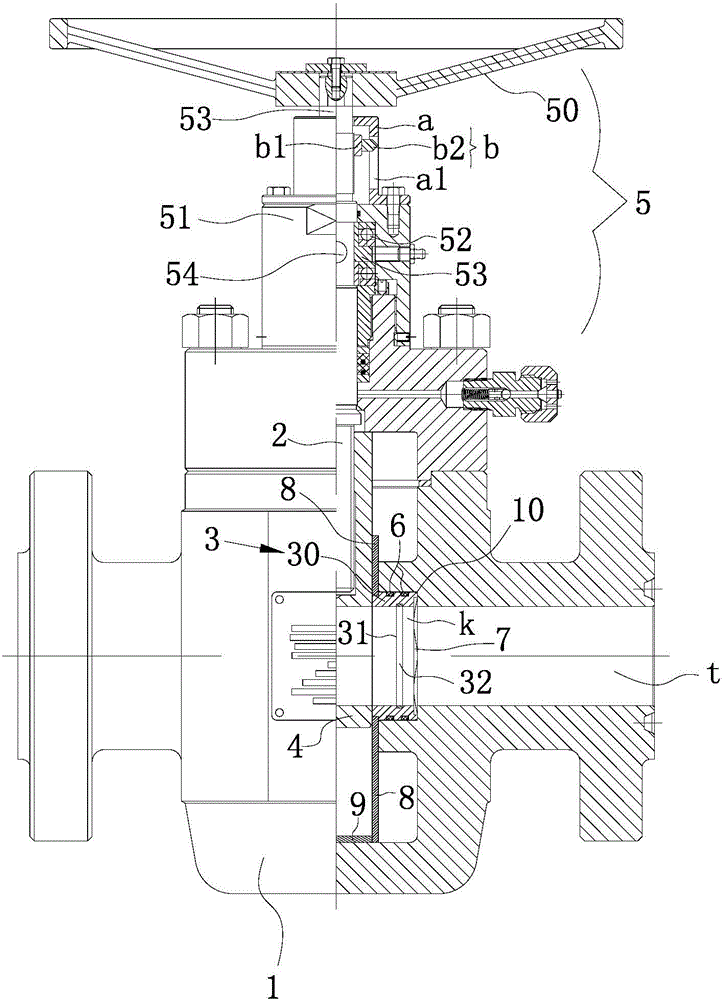
[0023] Such as figure 1 As shown, the slab gate valve with valve plate position indication function in this embodiment includes a valve body 1, a valve stem 2, a valve seat 3 sealed with the channel ports 10 on both sides inside the valve body 1, and valve seats located on both sides 3 and the valve plate 4 arranged on the valve stem 2, and the driving mechanism 5 for driving the valve stem 2 to rotate around its own axis so that the valve plate 4 moves up and down to intercept or open the channel, wherein the valve stem 2 and the valve plate 4 constitute a screw nut structure.

[0024] Specifically, the valve seat 3 includes a seat body 30 with a through hole k communicating with the channel t, an installation groove 31 disposed inside the seat body 30 around its circumference, and arranged in the installation groove 31 so that the valve seat 3 and the channel There is a tightening ring 32 with a tendency to tighten at the junction of the mouth 10.

[0025] Further, the out...


PUM


Abstract

The invention relates to a flat gate valve with a valve plate position indication function. The flat gate valve comprises a valve body, a valve rod, a valve seat, a valve plate and a drive mechanism for making the valve plate rise and fall so that a passageway can be blocked or opened. The drive mechanism comprises a hand wheel, a bearing pedestal, a shaft sleeve driven by the hand wheel and arranged on the bearing pedestal through a bearing, and a pin shaft used for oppositely locking the shaft sleeve and the valve rod. The valve seat comprises a seat body, an installation groove formed in the seat body in the circumferential direction of the seat body, and a tensioning ring arranged in the installation groove and making the connection position of the valve seat and an opening of the passageway have the tensioning tendency. The flat gate valve further comprises an indicator cover and a pointer arranged on the shaft sleeve in a sleeving manner and moving up and down along with rotation of the shaft sleeve, wherein the pointer and the valve plate synchronously move. Due to the fact that the tensioning ring is arranged, the leakproofness of the valve seat and the valve body can be high, and leakage accidents are reduced. Meanwhile, because the pointer and the valve plate synchronously move, the position of the valve plate can be directly judged, and control over the flowing speed is facilitated.

Description

technical field [0001] The invention relates to a flat gate valve, in particular to a flat gate valve with a valve plate position indicating function. Background technique [0002] As we all know, the slab gate valve, as a component used to realize the on-off and flow control of the pipeline system, is widely used in many fields such as oil, natural gas, and water conservancy. [0003] At present, the flat gate valve with valve plate position indication function basically includes a valve body, a valve stem, and a valve seat that is sealed with the passage openings on both sides inside the valve body, and is located between the valve seats on both sides and is arranged on the valve body. The valve plate on the rod, and the driving mechanism for driving the valve rod to rotate around its own axis so that the valve plate moves up and down to intercept or open the channel, wherein the valve rod and the valve plate form a screw nut structure, the two sides of the valve plate ar...

Claims


Application Information

Patent Timeline
Patent Type & Authority Applications(China)
IPC IPC(8): F16K3/16F16K37/00
CPCF16K3/16F16K37/0008
Inventor 徐丽霞张跃进吴平徐诚王海宾
Owner US DIAMOND OIL DRILLING SYST ENG (SHANGHAI) CO LTD
Why Eureka
Try Eureka