
A Non-Uniform Microstrip-to-Stripline Transition Structure

A transitional structure and microstrip line technology, applied in the direction of waveguides, electrical components, connecting devices, etc., can solve the problem that the structure cannot be applied to the non-uniform microstrip line structure, etc., to improve standing wave characteristics, strong flexibility, and application occasions. wide effect

Active Publication Date: 2019-10-11
SHANGHAI SPACEFLIGHT INST OF TT&C & TELECOMM
View PDF2 Cites 0 Cited by
  • Summary
  • Abstract
  • Description
  • Claims
  • Application Information

AI Technical Summary

Problems solved by technology

[0004] After searching the existing microstrip-to-stripline transition structure, it was found that, for example, the information communication published in the second issue of 2016 (KU-band LTCC substrate microstrip stripline vertical interconnection design), IEEE TRANS.ON MICROWAVE AND Published in THEORYTECHNOLOGY Volume 53 (High Performances of Shielded LTCC Vertical Transitions From DC to 50GHz), both of them realize the transition structure from uniform microstrip line to stripline by loading LTCC process, but the structure cannot be applied to non-uniform microstrip line structure

Method used


Image

  • A Non-Uniform Microstrip-to-Stripline Transition Structure
  • A Non-Uniform Microstrip-to-Stripline Transition Structure
  • A Non-Uniform Microstrip-to-Stripline Transition Structure

Examples


Embodiment Construction

[0033] The embodiments of the present invention are described in detail below. This embodiment is implemented on the premise of the technical solution of the present invention, and detailed implementation methods and specific operating procedures are provided, but the protection scope of the present invention is not limited to the following implementation example.

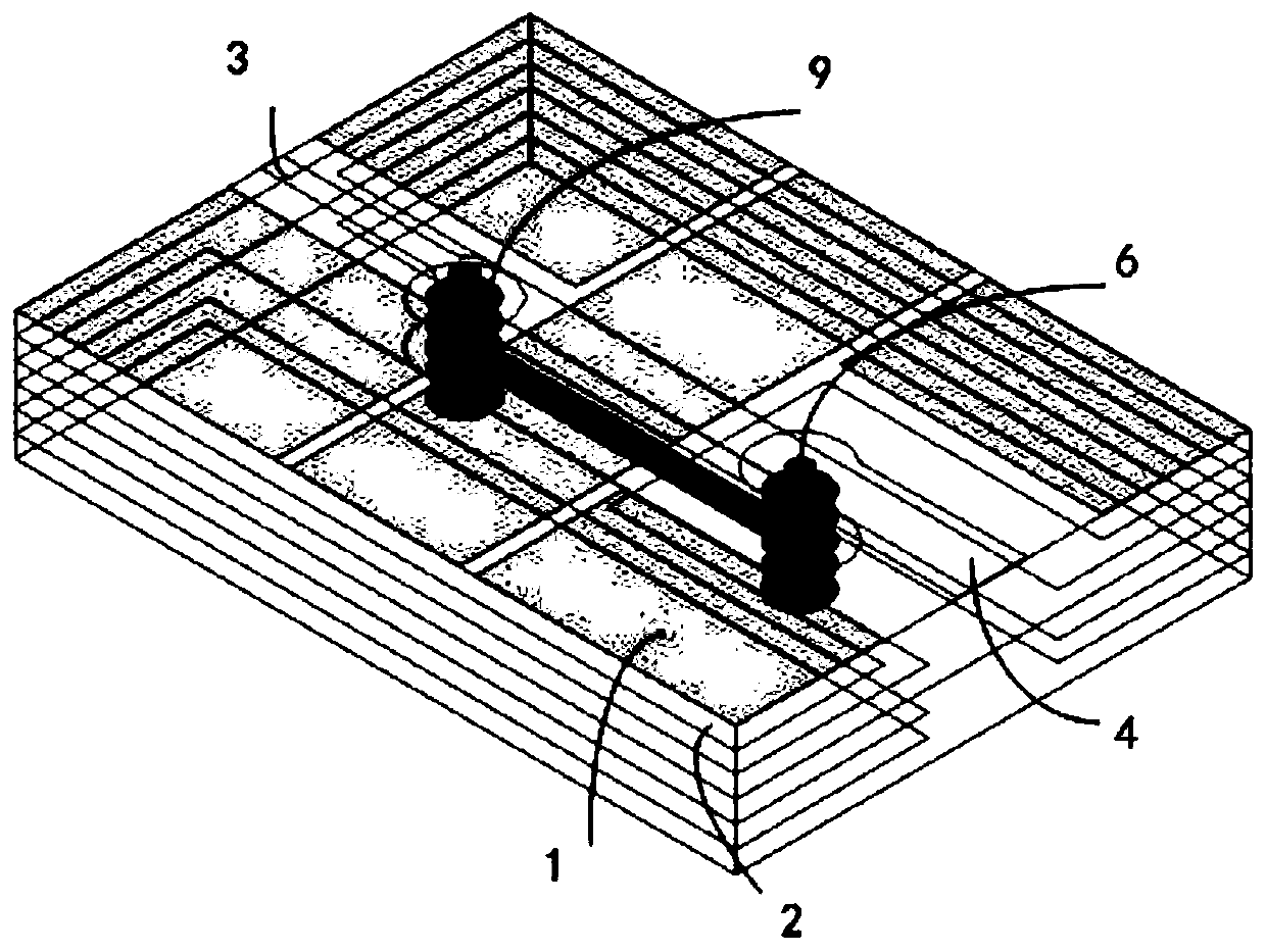
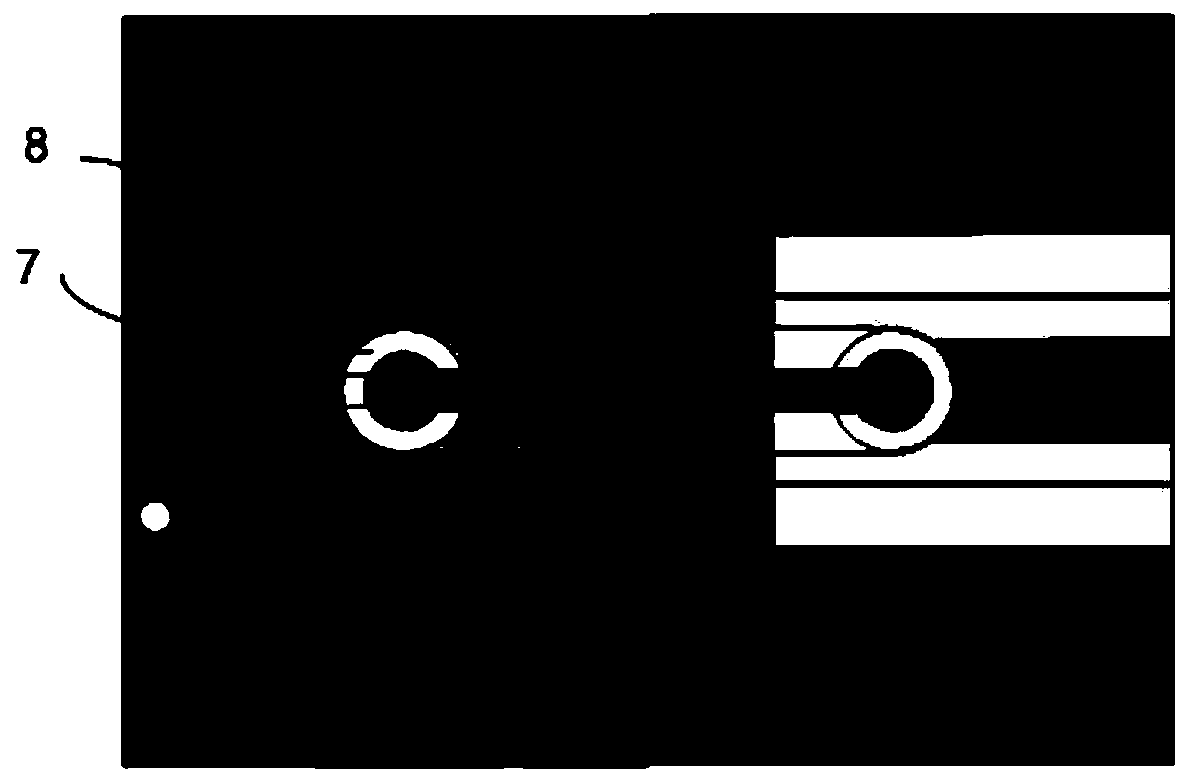
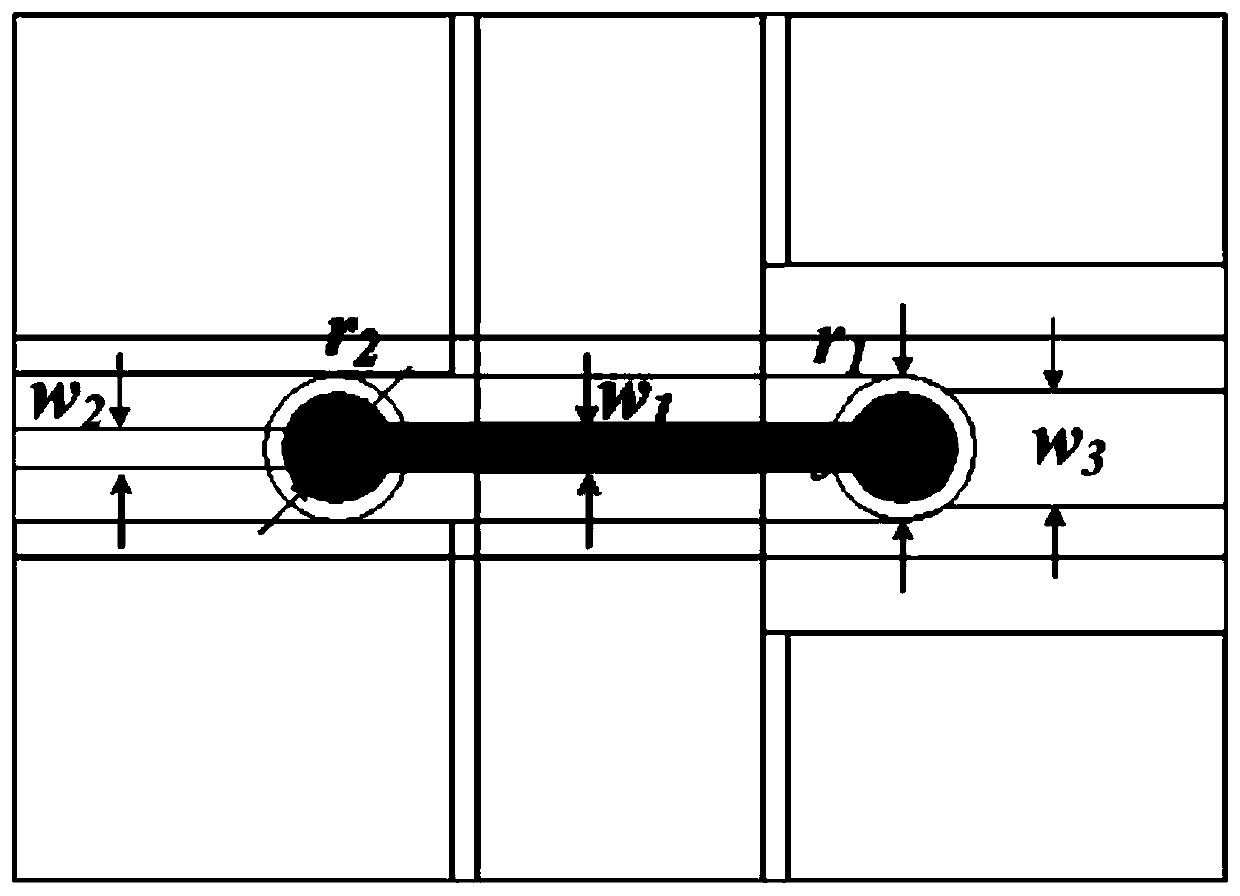
[0034] to combine Figure 1-Figure 7 , the non-uniform microstrip line to stripline transition structure of the present invention is described in detail, which includes: a metal layer and a dielectric layer, the number of metal layers is N, N≥4, N layers of metal layers are stacked in sequence, and the dielectric layer The number of layers is N-1, and the dielectric layer is set between every two adjacent metal layers; it also includes: non-uniform input microstrip lines, non-uniform output microstrip lines, striplines, circular slots, and signal blind holes ; The non-uniform input microstrip line and the non-unif...


PUM


Abstract

The invention discloses a transition structure from a non-uniform microstrip line to a strip line. The structure comprises metal layers and dielectric layers, wherein the number of the metal layers is N; N is greater than or equal to 4; the N metal layers are stacked in sequence; the number of the dielectric layers is N-1; each dielectric layer is arranged between every two adjacent metal layers; the structure further comprises a non-uniform input microstrip line, a non-uniform output microstrip line, a strip line, a circular groove and a signal blind hole; the non-uniform input microstrip line and the non-uniform output microstrip line are arranged on the first metal layer; when the number N of the metal layers is equal to 4, the strip line is arranged on the third metal layer, and the circular groove is formed in the second metal layer; when the number of the metal layers is greater than 4, the strip line is arranged in any metal layer from the third metal layer to the N-1 metal layer, and the circular groove is formed in any metal layer from the second metal layer to the metal layer in which the strip line is arranged; the vertical projection of the signal blind hole is positioned in the vertical projection of the circular groove; the signal blind hole is used for connecting the strip line with a non-uniform input microstrip line and a non-uniform output microstrip line. The structure can be applied to non-uniform microstrip line structures.

Description

technical field [0001] The invention relates to a radio frequency signal transition structure in a microwave transceiver module, in particular to a transition structure from a non-uniform microstrip line to a stripline. Background technique [0002] The multi-function, miniaturization, short development cycle and low cost of electronic information system are the requirements constantly put forward by system users, and it has always been its development direction. Taking personal mobile communication as an example, the size of mobile phones has shrunk from the "brick" in the 1990s to the size of a business card box today, and its functions have expanded from simple calls at that time to voice, data, multimedia, Internet, photography, and MP3. The multi-functionalization and miniaturization of military electronic information systems (such as spaceborne information acquisition and processing systems) are the focus of attention. [0003] The microstrip line is a transmission li...

Claims


Application Information

Patent Timeline
Patent Type & Authority Patents(China)
IPC IPC(8): H01P3/18H01P5/08
Inventor 沈玮李振海陈凯化宁刘宇张理正
Owner SHANGHAI SPACEFLIGHT INST OF TT&C & TELECOMM
Learn More