Unipolar microstrip oscillator

A unipolar microstrip and microstrip technology, applied in the field of communication, can solve problems such as unsatisfactory, and achieve the effect of excellent communication electrical parameter performance

Inactive Publication Date: 2016-11-23
陈小华
View PDF0 Cites 1 Cited by
  • Summary
  • Abstract
  • Description
  • Claims
  • Application Information

AI Technical Summary

Problems solved by technology

The antenna can be regarded as a tuned circuit composed of capacitance and inductance; at certain frequency points, the capacitance and inductance of the tuned circuit will cancel each other out, and the circuit will show pure resistance. This phenomenon is called resonance, and the resonance phenomenon corresponds to The working frequency point is the resonant frequency point, and the energy at the resonant frequency point of the antenna has the strongest radiation characteristics; the antenna structure with resonant characteristics is called an antenna oscillator, and the antenna structure directly excited by high-frequency current is called an active Vibrator, otherwise called passive vibrator; existing vibrator, including physical vibrator and microstrip vibrator, when designing the antenna according to the needs of actual use, in order to make the resonant frequency point of the antenna meet the set requirements, it is necessary to adjust the resonant frequency point of the antenna The input impedance is adjusted. The adjusted oscillator and the ordinary oscillator still cannot meet the requirements of the current communication standard. The current communication standard is getting higher and higher, and the requirements for the microstrip oscillator are also getting higher and higher. The gain and directivity of the current oscillator , front-to-back ratios need breakthroughs, and the most important thing is to achieve the above-mentioned breakthroughs under the premise of miniaturization

Method used


Image

  • Unipolar microstrip oscillator
  • Unipolar microstrip oscillator
  • Unipolar microstrip oscillator

Examples


Embodiment Construction

[0037] The present invention will be described in further detail below in conjunction with the accompanying drawings and specific embodiments, and the implementation scope of the present invention is not limited thereto.

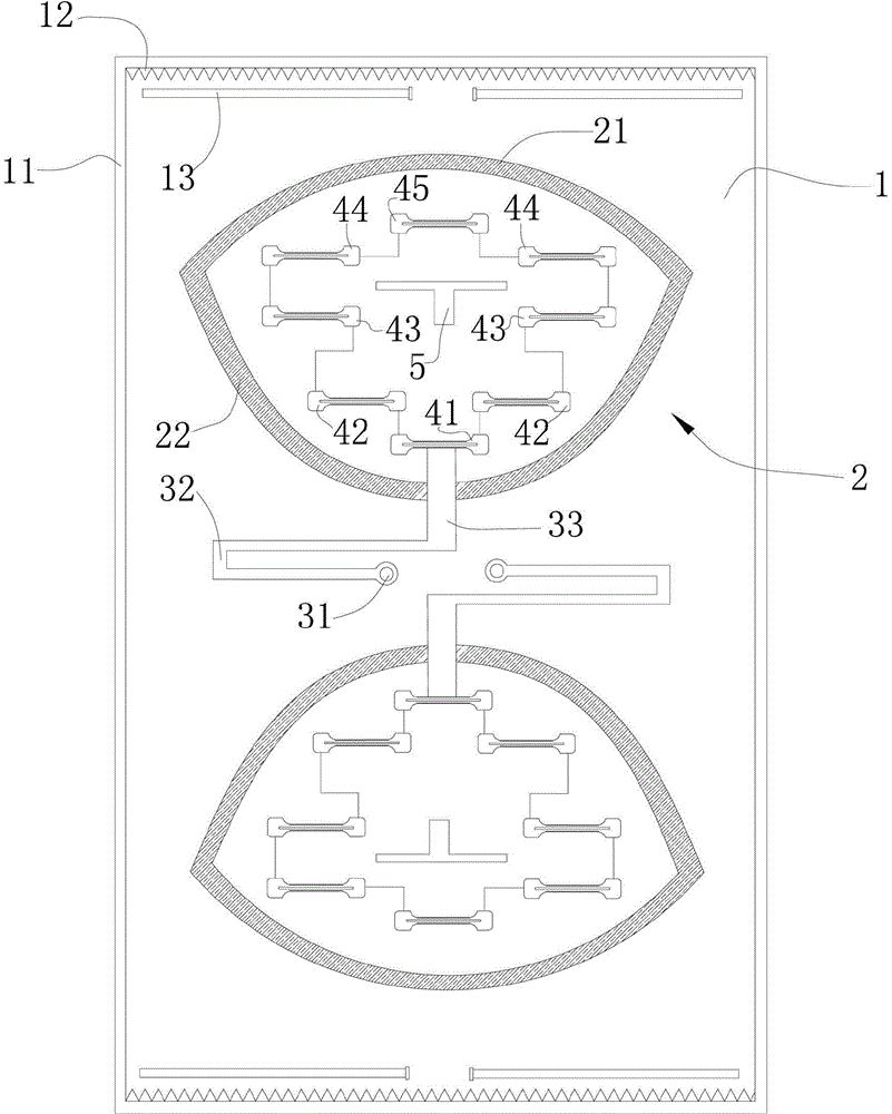
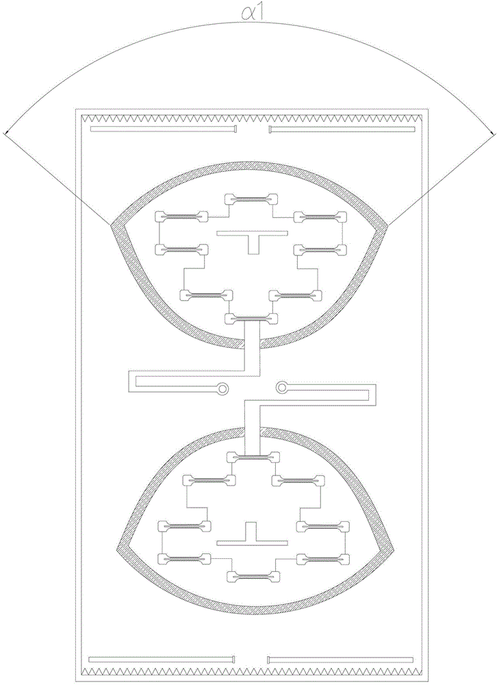
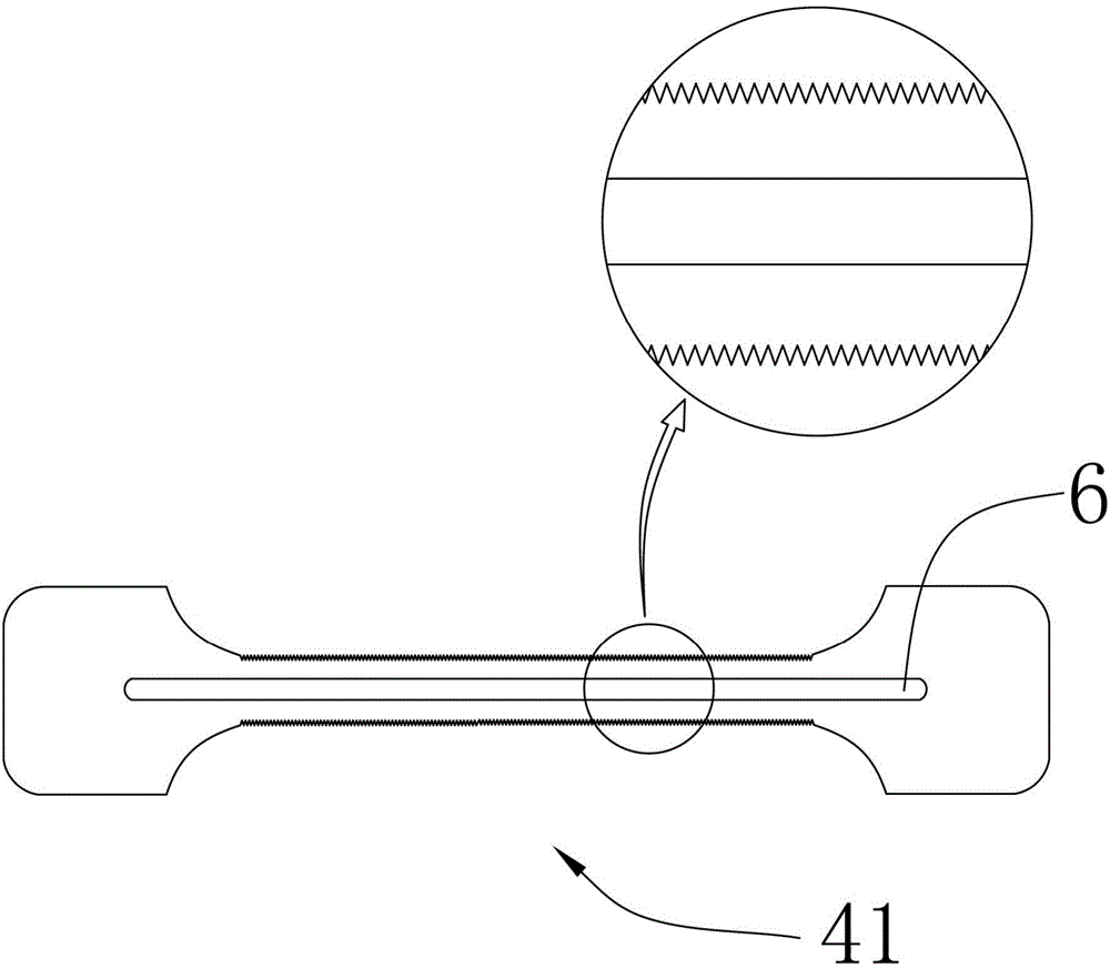
[0038] Such as Figure 1 to Figure 11 As shown, a kind of unipolar microstrip vibrator described in this embodiment includes a main PCB board 1, and two microstrip radiation regions 2 are symmetrically arranged on the main PCB board 1; Zone 2 includes a microstrip upper arc edge 21 and a microstrip lower arc edge 22, and the microstrip upper arc edge 21 and the microstrip lower arc edge 22 are closed to form a closed area; each microstrip radiation area 2 There are multiple independent half-wavelength microstrip units; each of the microstrip units is dumbbell-shaped with wide ends and a narrow middle; the multiple independent half-wavelength microstrip units are divided into a first A microstrip unit 41, two second microstrip units 42, two third microstrip ...


PUM


Abstract

The invention relates to the field of communication, in particular to a unipolar microstrip oscillator. The unipolar microstrip oscillator comprises a main PCB, wherein two microstrip radiation regions are symmetrically arranged on the main PCB; each microstrip radiation region comprises a microstrip upper arc side and a microstrip lower arc side, and the microstrip upper arc side and the microstrip lower arc side are closed to form a closed region; a plurality of independent microstrip units each of which has a half wavelength are arranged in each microstrip radiation region; and each microstrip unit is wide at two ends and narrow in the middle and is in a dumbbell shape. The unipolar microstrip oscillator shows excellent communication electrical parameter performance in the frequency band from 800 MHz to 950 MHz, specifically, the front-to-back ratio at the lowest frequency point of each single radiation unit is greater than 31 dB, and the front-to-back ratio at the lowest frequency point of each single radiation unit at 950 MHz is 36 dB; and the gain of the low frequency points is greater than 9.35 dBi, and the average gain in the band is greater than 9.8 dBi.

Description

technical field [0001] The invention relates to the communication field, in particular to a unipolar microstrip vibrator. Background technique [0002] At present, micro-single antennas have become the mainstream of communication, especially miniaturized antennas. An antenna is a device that converts high-frequency current into radio waves and transmits them into space, and at the same time collects space radio waves and generates high-frequency currents. The antenna can be regarded as a tuned circuit composed of capacitance and inductance; at certain frequency points, the capacitance and inductance of the tuned circuit will cancel each other out, and the circuit will show pure resistance. This phenomenon is called resonance, and the resonance phenomenon corresponds to The working frequency point is the resonant frequency point, and the energy at the resonant frequency point of the antenna has the strongest radiation characteristics; the antenna structure with resonant char...

Claims


Application Information

Patent Timeline
IPC IPC(8): H01Q13/08H01Q1/36H01Q1/38
Inventor 陈小华
Owner 陈小华
Why Eureka
Try Eureka