
Electronic equipment in wireless communication system and wireless communication method

A technology of wireless communication systems and electronic equipment, applied in radio transmission systems, diversity/multi-antenna systems, transmission systems, etc., to achieve the effect of improving transmission performance

Active Publication Date: 2016-11-23
SONY CORP
View PDF5 Cites 3 Cited by
  • Summary
  • Abstract
  • Description
  • Claims
  • Application Information

AI Technical Summary

Problems solved by technology

[0006] In the 3D MIMO system, due to the use of 2D antenna arrays, the original notification unit for 1D antenna array information is no longer applicable

Method used


Image

  • Electronic equipment in wireless communication system and wireless communication method
  • Electronic equipment in wireless communication system and wireless communication method
  • Electronic equipment in wireless communication system and wireless communication method

Examples


Embodiment Construction

[0031] Examples of the present disclosure will now be described more fully with reference to the accompanying drawings. The following description is merely exemplary in nature and is not intended to limit the disclosure, application or uses.

[0032] Example embodiments are provided so that this disclosure will be thorough, and will fully convey the scope to those who are skilled in the art. Numerous specific details are set forth such as examples of specific components, devices and methods, to provide a thorough understanding of embodiments of the present disclosure. It will be apparent to those skilled in the art that specific details need not be employed, that example embodiments may be embodied in many different forms, and that neither should be construed to limit the scope of the disclosure. In some example embodiments, well-known processes, well-known structures, and well-known technologies are not described in detail.

[0033] The UE (User Equipment, user equipment) i...


PUM


Abstract

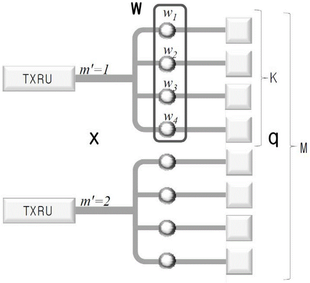
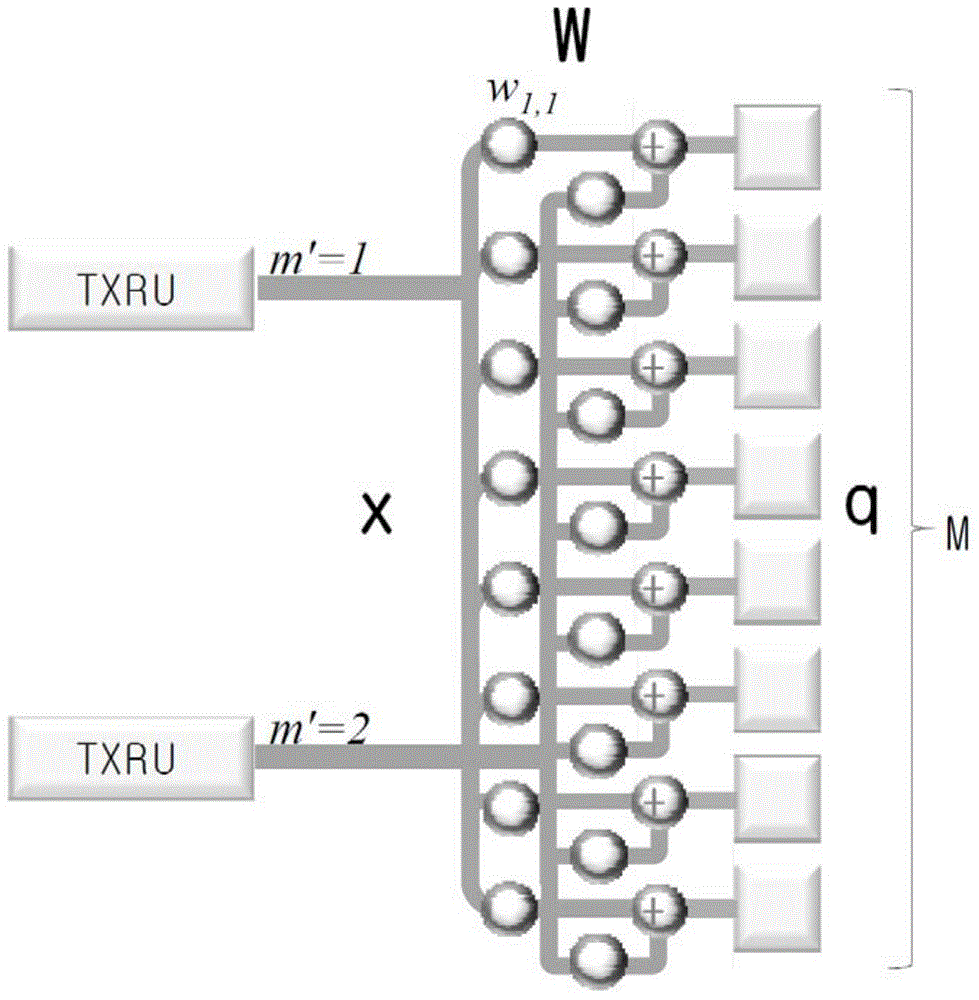
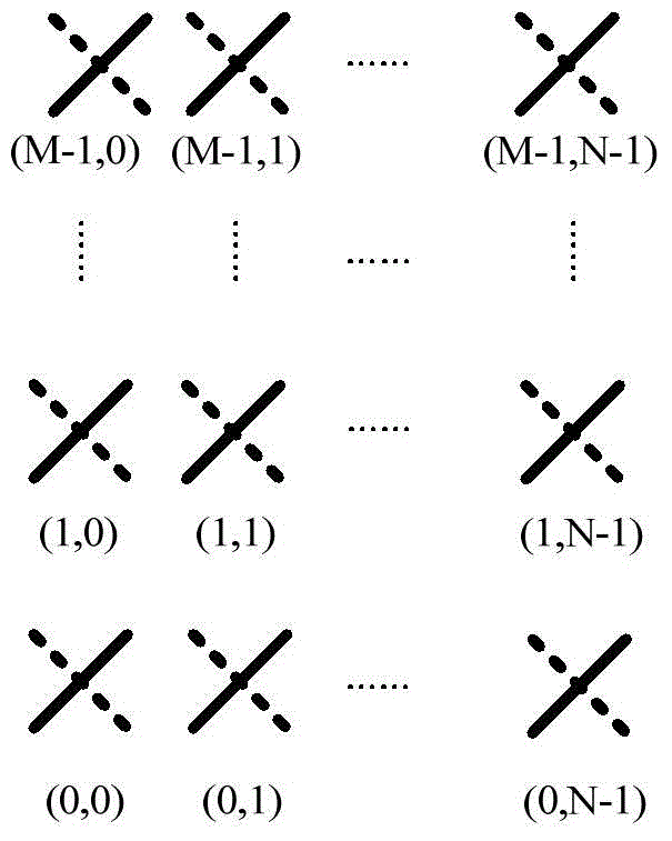
The invention relates to electronic equipment in a wireless communication system and a wireless communication method. The electronic equipment comprises one or more processing circuits and user equipment, wherein each processing circuit is configured to execute the following operations of determining configuration of a corresponding transceiver unit TXRU based on an antenna array corresponding to the electronic equipment, wherein each TXRU is related to one group of antenna units having the same polarization direction, the antenna array is provided with M rows and N columns of antenna units in a P-dimensional polarization direction, and M, N and P are natural numbers; and adding antenna configuration information into radio resource control RRC signaling to be used for user equipment in the wireless communication system, wherein the antenna configuration information is used for obtaining number of TXRUs in the antenna array. According to the electronic equipment and the wireless communication method which are disclosed by the invention, the user equipment can obtain the antenna configuration of a base station, so that when the user equipment estimates and measures a channel, the user equipment can conform to the configuration of the base station, and thus the transmission performance of a 3D MIMO (Multiple-Input Multiple-Output) system is improved.

Description

technical field [0001] The present disclosure relates to the technical field of wireless communication, and in particular to an electronic device in a wireless communication system and a method for performing wireless communication in the wireless communication system. Background technique [0002] This section provides background information related to the present disclosure which is not necessarily prior art. [0003] With the development of communication technology, research on vertical beamforming / FD MIMO (Full-Dimension Multiple-Input Multiple-Output, full-dimensional multiple-input multiple-output) in LTE (Long Term Evolution, long-term evolution) has been started. Among them, the difference between the vertical beamforming / FDMIMO and the traditional transmission system lies in the introduction of the vertical dimension and the use of more antennas. [0004] Meanwhile, with the introduction of the vertical dimension, a 2D antenna array is further proposed. In additio...

Claims


Application Information

Patent Timeline
Patent Type & Authority Applications(China)
IPC IPC(8): H04B7/04
CPCH04B7/0413H04B7/0469H04B7/0626H04B7/0639H04B7/0617H04B7/0421
Inventor 李高斯陈晋辉张欣韦再雪李南希
Owner SONY CORP
Learn More