Vibration energy harvester

A vibration energy harvesting, vibrating plate technology, applied in generators/motors, piezoelectric effect/electrostrictive or magnetostrictive motors, electrical components, etc., can solve the problem of easy breaking of piezoelectric cantilever beams

Inactive Publication Date: 2016-11-30
SYSU CMU SHUNDE INT JOINT RES INST +1
View PDF3 Cites 9 Cited by
  • Summary
  • Abstract
  • Description
  • Claims
  • Application Information

AI Technical Summary

Problems solved by technology

The traditional straight cantilever vibration energy harvester will reduce the resonance frequency by increasing the length of the piezoelectric ca

Method used


Image

  • Vibration energy harvester
  • Vibration energy harvester
  • Vibration energy harvester

Examples


Embodiment Construction

[0022] Embodiments of the present invention are described in detail below:

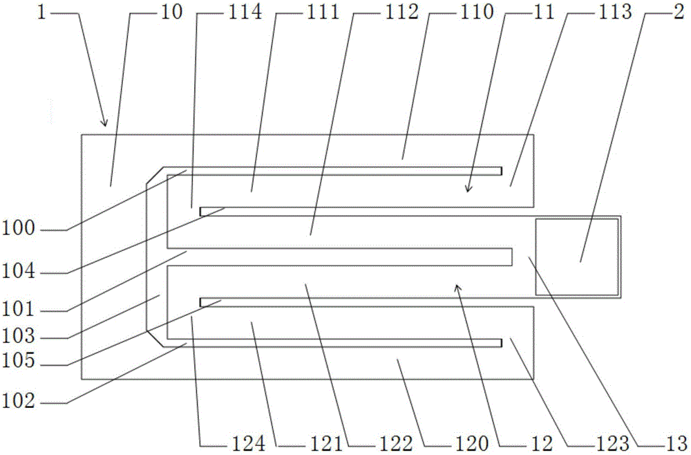
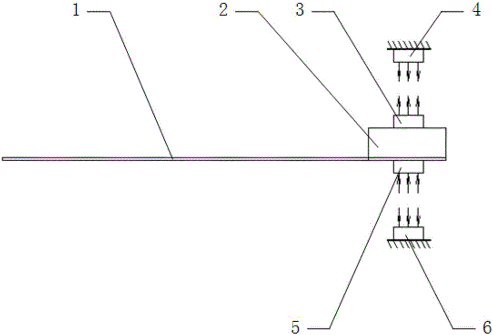
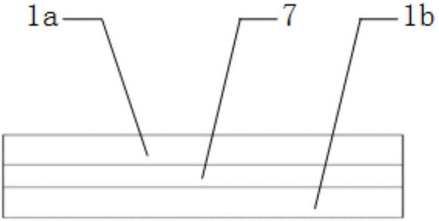
[0023] Such as Figure 1-3 As shown, the vibration energy harvester described in this embodiment includes a piezoelectric cantilever beam 1 and a mass block 2, and the piezoelectric cantilever beam 1 includes a fixed plate 10, a first detour plate 11, a second detour plate 12 and a vibration plate 13, the fixed plate 10 and the vibrating plate 13 are arranged at intervals, the first detour plate 11 is opposite to the second detour plate 12, one end of the first detour plate 11 is connected to the fixed plate 10, the first The other end of the detour plate 11 is detoured towards the direction close to the second detour plate 12 and connected to the vibrating plate 13, one end of the second detour plate 12 is connected to the fixed plate 10, and the other end of the second detour plate 12 is close to The direction of the first detour plate 11 is detoured and connected with the vibrating plate 13 , and ...


PUM


Abstract

The invention discloses a vibration energy harvester. The vibration energy harvester comprises a piezoelectric cantilever beam and a quality block, wherein the piezoelectric cantilever beam comprises a fixed plate, a first circuitous plate, a second circuitous plate and a vibration plate; the fixed plate and the vibration plate are separately arranged; the first circuitous plate and the second circuitous plate are oppositely arranged; one end of the first circuitous plate is connected with the fixed plate; the other end of the first circuitous plate is circuitous along a direction toward the second circuitous plate and is connected with the vibration plate; one end of the second circuitous plate is connected with the fixed plate; the other end of the second circuitous plate is circuitous along a direction toward the first circuitous plate and is connected with the vibration plate; and the quality block is fixed on the vibration plate. According to the vibration energy harvester, the fixed plate and the vibration plate are connected through the first circuitous plate and the second circuitous plate; compared with the traditional straight cantilever vibration energy harvesters with the same size, the vibration energy harvester of such a structure has the advantages of decreasing the widths of actual cantilevers, and being easier to sense the vibration and lower in resonant frequency.

Description

technical field [0001] The invention relates to the technical field, in particular to a vibration energy harvester. Background technique [0002] As the energy problem becomes more and more severe, it has become a hot research topic to seek a system that can collect the surrounding environmental energy and convert it into electrical energy. Mechanical vibration in the environment is ubiquitous, it is not affected by geographical location and climate, and there are vibration sources in many places that are difficult to enter, so the collection of vibration energy is more convenient and has a good development prospect. A vibration energy harvester is a device that converts mechanical energy generated by vibration into electrical energy. In a general environment, the vibration frequency of the vibration source is around 1-200Hz. Only when the vibration frequency of the vibration source is equal to the resonance frequency of the piezoelectric cantilever beam can the generated v...

Claims


Application Information

Patent Timeline
IPC IPC(8): H02N2/18
CPCH02N2/18H02N2/186
Inventor 崔若男叶涛
Owner SYSU CMU SHUNDE INT JOINT RES INST
Why Eureka
Try Eureka