Luggage article with foldable base assembly
A technology for luggage and articles, which is applied in the field of luggage and articles with foldable base components, and can solve the complex and challenging problems of casters or self-rotating wheel assemblies
- Summary
- Abstract
- Description
- Claims
- Application Information
AI Technical Summary
Problems solved by technology
Method used
Image

Examples
Embodiment Construction
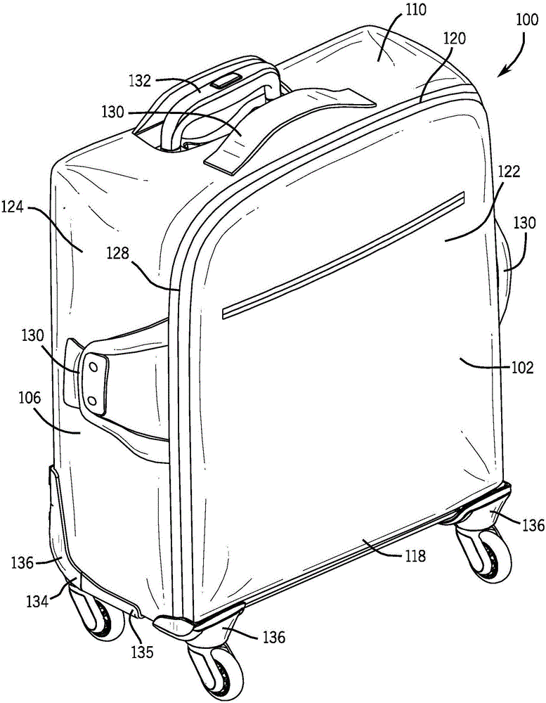
[0042] refer to figure 1 According to one embodiment, the wheeled luggage item 100 comprises a generally cuboidal structure formed by a plurality of walls defining an enclosed volume of the luggage item 100 in which belongings of a user are carried. This item of luggage can be found at figure 1 The fully operable open position shown in the Figure 4 Change between the folded positions shown in . As described below, the base assembly is collapsible to allow luggage item 100 to be moved between these two positions. The luggage item 100 includes opposing front and rear walls 102 , 104 , opposing left and right side walls 106 , 108 , and opposing top and bottom end walls 110 , 112 that together define a receptacle or exterior structure for the luggage case 100 . The exterior structure of the luggage item 100 defines a height, width and depth. Each of the walls 102, 104, 106, 108, 110, 112 may be referred to as a panel, face or side. For example, the front wall 102 and the rea...
PUM
 Abstract
Description
Claims
Application Information
 - R&D
- Intellectual Property
- Life Sciences
- Materials
- Tech Scout
- Unparalleled Data Quality
- Higher Quality Content
- 60% Fewer Hallucinations
Browse by: Latest US Patents, China's latest patents, Technical Efficacy Thesaurus, Application Domain, Technology Topic, Popular Technical Reports.
© 2025 PatSnap. All rights reserved.Legal|Privacy policy|Modern Slavery Act Transparency Statement|Sitemap|About US| Contact US: help@patsnap.com