Labor-saving stapler

A stapler and outer cover technology, applied in the direction of nailing staple tools, manufacturing tools, etc., can solve the problems of complex connection relationship, increase the manufacturing cost of staplers, etc., and achieve the effect of reducing manufacturing costs

Active Publication Date: 2016-12-07
SUNWOOD HLDG GROUP
View PDF8 Cites 1 Cited by
  • Summary
  • Abstract
  • Description
  • Claims
  • Application Information

AI Technical Summary

Problems solved by technology

[0004] Although the above-mentioned labor-saving stapler can achieve a good labor-saving effect during use, it still has some shortcomings: the labor-saving stapler needs to be connected between the iron cover and the connecting frame and between the connecting frame and the connecting frame during use. A labor-saving lever is formed between the tool holders to finally achieve labor-saving in use, which means that in order to achieve labor-saving, the setting of the connecting frame is essential, but adding an additional connecting frame will make the structure of the entire stapler and the relationship between the various parts more difficult. The connection relationship between becomes more complicated, and will increase the manufacturing cost of the whole stapler

Method used


Image

  • Labor-saving stapler
  • Labor-saving stapler
  • Labor-saving stapler

Examples


Embodiment 1

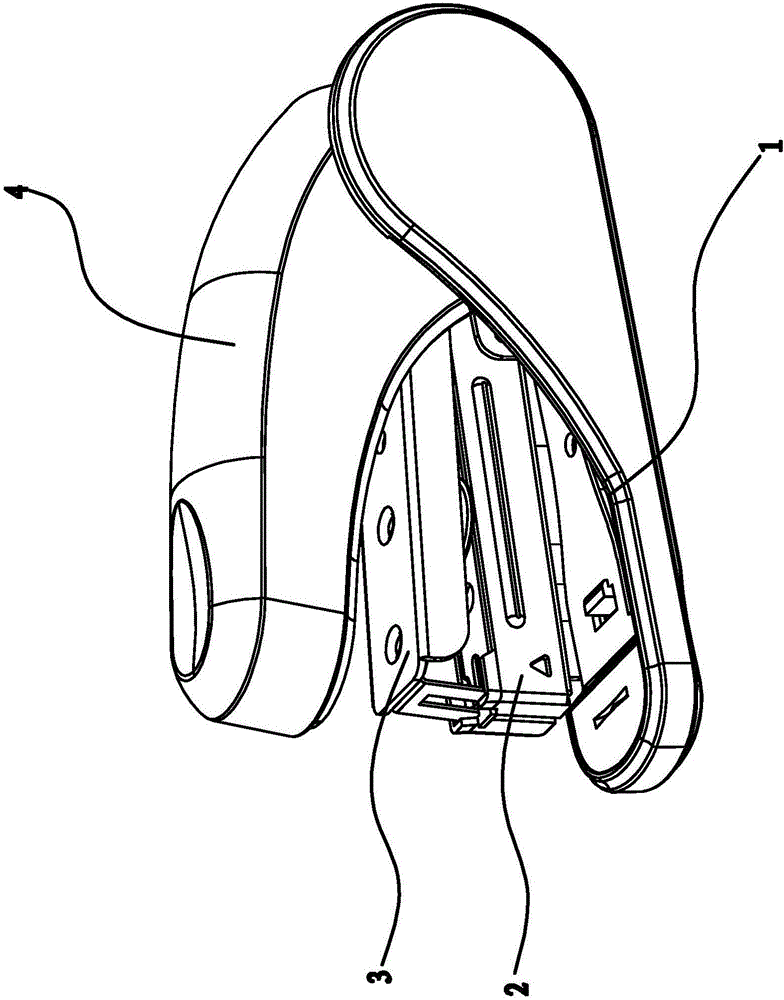
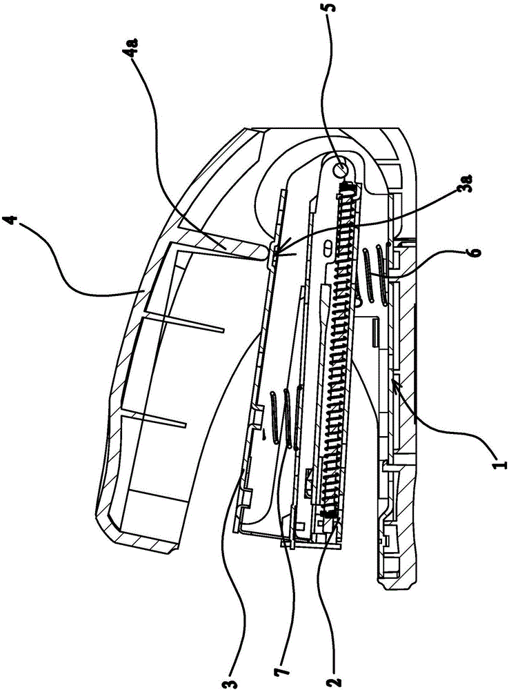
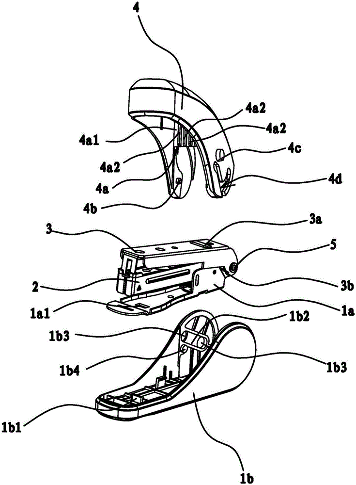
[0041] Such as figure 1 , figure 2 and image 3 As shown, the labor-saving stapler includes a bottom cover 1, a nail box 2, a press box 3, and an outer cover 4. The bottom cover 1 includes a bottom plate 1a and a plastic bottom 1b. The plastic bottom 1b has an upwardly protruding block 1b1, and the bottom plate A slot 1a1 is opened on 1a corresponding to the position of the block 1b1, and the block 1b1 is snapped into the slot 1a1 and buckled on the bottom plate 1a so that the floor is fixed on the plastic bottom 1b. The inner end of the nail box 2 and the inner end of the bottom plate 1a are hinged by the rear pin 5, and the inner end of the pressure box 3 is also hinged by the rear pin 5 and the inner end of the bottom plate 1a. There is a reset mechanism between the nail box 2 and the bottom plate 1a. A spring one 6, a return spring two 7 is arranged between the pressing box 3 and the nail box 2.

[0042] Such as image 3 , Figure 4 and Figure 5 As shown, the inner...

Embodiment 2

[0053] The structure and principle of this embodiment are basically the same as that of Embodiment 1, the difference is that in this embodiment, the upper surface of the raised portion 3a is a circular arc surface, and the action portion 4a includes a top inner wall formed by the inner end of the outer cover 4. The pressing plate 4a1 protruding downwards and several ribs 4a2 distributed on the side of the pressing plate 4a1 near the outer end of the outer cover 4, the lower surface of the pressing plate 4a1 and the ribs 4a2 are connected to form a flat slope, and the upper surface of the raised portion 3a is set The arc surface and the lower surface of the action part 4a are set as slopes, and when the action part 4a acts on the raised part 3a, it is ensured that the action part 4a and the raised part 3a will not interfere with each other, so that the outer cover 4 The pressing down of the pressing box 3 can be realized smoothly through the cooperation of the action part 4a and...

Embodiment 3

[0055] The structure and principle of this embodiment are basically the same as that of Embodiment 1, the difference is that in this embodiment, the linkage structure includes a stopper protruding from the inner side of the pressure box 3 and a stopper protruding from the inner end of the outer cover 4 The stopper on the inner wall, the stopper is located below the stopper head. When the outer end of the outer cover 4 is constantly opened outwards relative to the bottom cover 1, the stopper will swing to the lower side of the stopper against the inner end of the pressure box 3 along with the inner end of the outer cover 4, so that the stopper and The stoppers form against each other, and during the further outward opening process of the outer end of the outer cover 4 relative to the bottom cover 1, the stopper drives the pressure box 3 to turn outwards around the hinge point of the pressure box 3 and the bottom cover 1 , so that the labor-saving stapler can still have the func...


PUM


Abstract

The invention provides a labor-saving stapler, and belongs to the technical field of machines. The labor-saving stapler solves the problems that an existing labor-saving stapler is complex in connection relation, and high in manufacturing cost. The labor-saving stapler comprises a bottom cover, a staple box, a pressing box and an outer cover; the inner end of the staple box is hinged to the inner end of the bottom cover, the inner end of the pressing box is hinged to the inner end of the bottom cover, the inner end of the outer cover is connected with the inner end of the bottom cover, the outer end of the outer cover can be pressed downwards or opened outwards relative to the bottom cover, a protruding portion is arranged on the upper side of the inner end of the pressing box, an acting portion protruding outwards is arranged on the inner wall of the top of the inner end of the outer cover, and the lower end of the acting portion is located above the protruding portion; a linkage structure is arranged between the outer side of the inner end of the pressing box and the inner wall of the inner end of the outer cover; when the outer cover is opened outwards relative to the bottom cover, the pressing box can be driven by the linkage structure to turn over outwards around the hinge point of f the pressing box and the bottom cover; the labor-saving stapler has the beneficial effects that use of a connecting frame is omitted, the manufacturing cost is reduced, and meanwhile the functions of labor saving and normal staple containing are still achieved.

Description

technical field [0001] The invention belongs to the technical field of machinery and relates to a stapler, in particular to a labor-saving stapler. Background technique [0002] The stapler is a tool that people need to use frequently during their daily study and office work. The stapler can be used to bind each paper to avoid scattering. Traditional staplers need to exert greater pressure during use, especially when binding more paper or thicker paper, it takes a lot of effort to complete, and sometimes even cannot complete the binding. In order to bind easily, people have designed some labor-saving staplers, and these labor-saving staplers have utilized the principle of leverage to obtain a certain labor-saving effect in the binding process. [0003] For example, a labor-saving stapler [Application No.: 201310380024.X] proposed by the applicant, it includes a base, a nail path and a knife holder, the outer end of the knife holder is provided with a blade, the outer end of...

Claims


Application Information

Patent Timeline
Patent Type & Authority Applications(China)
IPC IPC(8): B25C5/02
CPCB25C5/025
Inventor 林夏森
Owner SUNWOOD HLDG GROUP
Why Eureka
Try Eureka