Rotary oil cylinder for lathe spindle box

A technology of a lathe spindle and a rotary oil cylinder, applied in the field of machinery, can solve the problems of inconvenient disassembly, inconvenient dismantling of a pipe and a piston, and inability to pull a pipe and a piston to rotate and dismantle, etc., and achieves the effect of improving the convenience of disassembly and assembly.

Pending Publication Date: 2018-02-16
郭必龙
View PDF2 Cites 4 Cited by
  • Summary
  • Abstract
  • Description
  • Claims
  • Application Information

AI Technical Summary

Problems solved by technology

For the case where the inner support chuck is used to clamp the workpiece, since the inner support chuck and the drawing tube are not directly threaded, but the inner support chuck is first knocked into the main shaft, and then the inner support The collet and the pull tube are connected together through a pull rod, and one end of the pull rod passes through the inner support chuck and is threaded into the hole on the outer end surface of the pull tube. In this case, the inner support chuck cannot External for disassembly
Then to disassemble the inner support chuck, the staff can only poke the drawing tube from the inner end of the drawing tube to the outer end of the drawing tube, so that the outer end of the drawing tube extends out of the main shaft together with the inner support chuck The inner support chuck can be disassembled, but to push the outer end of the pull tube out of the main shaft will inevitably involve the disengagement of the pull tube and the piston, otherwise the pull tube cannot be pushed out of the main shaft due to the stroke of the piston.
[0004] However, because the pistons of the existing rotary cylinders are all front-mounted, for example, the single-piston hollow rotary cylinder [application number: 201220220479.6] disclosed in the Chinese patent and a clamping mechanism for machining bars by CNC machine tools [application number : 201120214739.4] in the hollow rotary oil cylinder, that is, the outer end of the piston directly extends to the outer body of the oil cylinder through the hole on the outer end of the oil cylinder, and the inner end of the pull tube in the main shaft is directly inserted into the outer end of the piston and forms a connection. However, since the piston is located in the cylinder, and the outer end of the cylinder is connected with the inner end of the main shaft, it is impossible to directly rotate and remove the pull tube and the piston. Separate the pull tube from the piston, and to separate the pull tube from the piston, you need to disassemble the cylinder from the main shaft first, and then turn the pull tube to separate from the piston, which means that the rotary cylinder and the lathe The removal of other parts of the headstock is very inconvenient, especially the inconvenience of removing the pull tube and piston

Method used


Image

  • Rotary oil cylinder for lathe spindle box
  • Rotary oil cylinder for lathe spindle box
  • Rotary oil cylinder for lathe spindle box

Examples


Embodiment 2

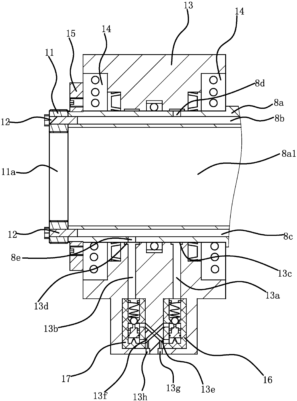
[0069] The structure and principle of this embodiment are basically the same as that of Embodiment 1. The difference is that in this embodiment, the mounting plate 11 is provided with a fixing hole that enables the mounting plate 11 to be screwed to the outside of the end of the mating portion 8a. The hole is connected with the mounting hole 11a and the fixing hole is coaxial with the mounting hole 11a. The fixing hole is opened on the outer end face of the mounting plate 11, and the mounting hole 11a is opened on the inner end face of the mounting plate 11, and the aperture of the fixing hole is larger than the mounting plate. The diameter of the hole 11a.

[0070] The mounting plate 11 is provided with a fixed hole with an aperture larger than the aperture of the mounting hole 11a. When the mounting plate 11 is used to connect the fitting portion 8a of the drawing tube 2 and the piston 8, one end of the mounting plate 11 provided with the fixing hole is passed through the dra...

Embodiment 3

[0072] The structure and principle of this embodiment are basically the same as that of Embodiment 1, the difference is that in this embodiment, one end of the mounting plate 11 is provided with a fixing hole that enables the mounting plate 11 to be screwed to the outside of the end of the mating portion 8a , the other end of the mounting plate 11 is provided with a relief hole that can be penetrated by the pull pipe 2 of the lathe headstock, the relief hole is connected with the fixing hole and is coaxial with the fixing hole, and the aperture of the fixing hole is larger than the letting hole. As for the diameter of the bit hole, the side of the mounting plate 11 is penetratingly provided with a fastening hole laterally communicating with the setback hole, and the fastening hole is internally threaded with a fastening screw.

[0073] When assembling, the mounting plate 11 is sleeved on the pull tube 2 through the relief hole, and then the mounting plate 11 is rotated, and the...


PUM


Abstract

The invention provides a rotary oil cylinder used for a spindle box of a lathe, which belongs to the technical field of machinery. It solves the problem of inconvenient disassembly of the existing rotary oil cylinder. The rotary oil cylinder used for the lathe headstock includes a cylinder body, the cylinder body is provided with a mating end and a mounting end for connecting with the main shaft of the lathe headstock, a movable piston is arranged in the cylinder body, and a protrusion is provided at one end of the piston. The matching part extends out of the matching end of the cylinder and is detachably connected to the mounting plate at the end of the matching part. The pull tube of the lathe headstock can pass through the matching part and the mounting plate in turn and form a detachable joint with the mounting plate. connect. It has the advantages of convenient disassembly and assembly and simple structure.

Description

technical field [0001] The invention belongs to the technical field of machinery, and relates to a rotary oil cylinder used for a spindle box of a lathe. Background technique [0002] A lathe is a machine tool that mainly uses a turning tool to turn a rotating workpiece. On the lathe, a drill bit, a reamer, a reamer, a screw tap, a die and a knurling tool, etc. can also be used for corresponding processing. The existing lathe spindle box usually includes a box body and a rotary oil cylinder. A hollow piston rod is arranged in the rotary oil cylinder. A main shaft and a drawing tube are arranged in the box body. There is a collet at one end, the cylinder body of the rotary cylinder is connected with the main shaft, one end of the pull tube extends into the hollow piston rod and connects with the hollow piston rod, the other end of the pull tube is connected with the collet, and the hollow piston rod drives the collet through the pull tube The workpiece is clamped and the chu...

Claims


Application Information

Patent Timeline
Patent Type & Authority Applications(China)
IPC IPC(8): B23B19/00B23Q3/08
CPCB23Q1/70B23Q3/08B23Q3/082
Inventor 郭必龙
Owner 郭必龙
Why Eureka
Try Eureka