
Tire condition detection method and device

A state detection and tire technology, applied in tire measurement, automobile tire testing, tire parts, etc., to achieve the effect of a safe driving environment

Active Publication Date: 2018-10-30
SHENZHEN SMARTSAFE TECH CO LTD
View PDF3 Cites 0 Cited by
  • Summary
  • Abstract
  • Description
  • Claims
  • Application Information

AI Technical Summary

Problems solved by technology

[0003] The main purpose of the present invention is to provide a tire state detection method and device, aiming to solve the technical problem of more comprehensive detection of various tire states under the driving state of the vehicle

Method used


Image

  • Tire condition detection method and device
  • Tire condition detection method and device
  • Tire condition detection method and device

Examples


Embodiment Construction

[0031] It should be understood that the specific embodiments described here are only used to explain the present invention, not to limit the present invention.

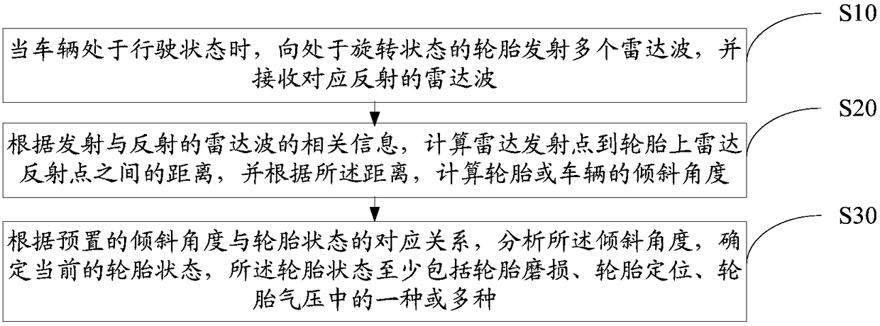
[0032] refer to figure 1 , figure 1 It is a schematic flowchart of an embodiment of the tire condition detection method of the present invention. In this embodiment, the tire condition detection method includes:

[0033] Step S10, when the vehicle is in the driving state, transmit a plurality of radar waves to the tires in the rotating state, and receive corresponding reflected radar waves;

[0034] In this embodiment, there is no limit to the number, installation location, type of radar wave, and radar emission mode of the radar transceiver devices, and they are specifically set according to actual needs. For example, each wheel or each group of wheels corresponds to a radar transceiver; for example, the radar transceiver is installed on the chassis of the vehicle.

[0035] Usually, changes in the state of the ti...


PUM


Abstract

Provided are a tyre state detection method and a corresponding detection device. The method comprises: when a vehicle is in a driving state, transmitting a plurality of radar waves to a tyre in a rotating state, and receiving corresponding reflected radar waves; calculating, according to information of the transmitted radar waves and the reflected radar waves, a distance between a radar transmission point and a corresponding radar reflection point on the tyre, and calculating an inclination angle of the tyre or the vehicle according to the distance; and analyzing, according to a preset correspondence between the inclination angle and a tyre state, the inclination angle, and determining a current tyre state, wherein the tyre state comprises at least one or more of tyre abrasion, tyre positioning and tyre pressure. According to the tyre state detection method and device, a tyre state can be determined during driving of a vehicle, so that a safe driving environment is provided for an owner of the vehicle.

Description

technical field [0001] The invention relates to the technical field of vehicle detection, in particular to a tire state detection method and device. Background technique [0002] The good condition of tires is the primary guarantee for safe driving of vehicles. In the existing tire state detection technology, it is usually carried out when the vehicle is in a static state, and most of them are detected by manual identification. In actual situations, users have a very high demand for understanding the tire status even in the driving state, but the existing methods can only realize the detection of a certain type of tire status, such as tire pressure, tire temperature detection, etc. Therefore, it is impossible to understand the various states of the tire more comprehensively. Contents of the invention [0003] The main purpose of the present invention is to provide a tire state detection method and device, aiming at solving the technical problem of more comprehensive dete...

Claims


Application Information

Patent Timeline
Patent Type & Authority Patents(China)
IPC IPC(8): B60C23/06G01M17/02
CPCB60C23/06G01M17/02
Inventor 刘均刘新宋朝忠欧阳张鹏
Owner SHENZHEN SMARTSAFE TECH CO LTD
Learn More