Flash relay for controlling flicker of LED steering lamp and control method

A technology of LED turn signals and flashing relays, which is applied to electrical components and other directions, can solve the problems of inability to control motorcycle LEDs and LED and incandescent lights mixed with corresponding state flashing lights, and inability to provide overvoltage protection for LED and incandescent turn lights. Achieve the effect of ensuring the life of the lamp, avoiding the decline of the life, and the working mode is accurate

Active Publication Date: 2021-10-19
CHONGQING HECHENG ELECTRIC APPLIANCE
View PDF7 Cites 0 Cited by
  • Summary
  • Abstract
  • Description
  • Claims
  • Application Information

AI Technical Summary

Problems solved by technology

[0006] In view of the above-mentioned deficiencies existing in the prior art, the purpose of the present invention is to solve the problem that the existing flash relay cannot control the motorcycle LED and the LED and incandescent lamp hybrid steering lamps to flicker in the corresponding state, and cannot perform overvoltage protection on the LED and incandescent lamp steering lamps. problem; to provide a flash relay and control method for controlling the flickering of LED turn signal lamps, which can identify the working current of LED and LED and incandescent lamp mixed steering lamps, so as to accurately determine whether the steering lamps are normal lamps or whether there is an abnormal state, and control The steering lamps perform corresponding flashing modes; at the same time, when the input is overvoltage, it can be controlled by the action of the flashing relay to avoid the overvoltage operation of the steering lamps, thereby avoiding the shortened life and damage of the steering lamps

Method used


Image

  • Flash relay for controlling flicker of LED steering lamp and control method
  • Flash relay for controlling flicker of LED steering lamp and control method
  • Flash relay for controlling flicker of LED steering lamp and control method

Examples


Embodiment

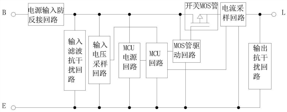
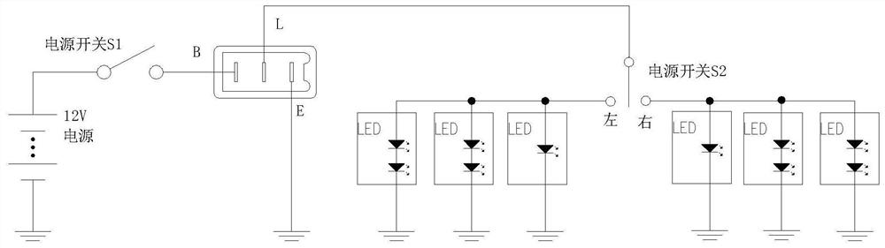
[0032] Example: see Figure 1 to Figure 2 , a flashing relay for controlling the flickering of LED turn signals, including an MCU loop, an input voltage sampling loop, an MCU power supply loop, an input terminal B, and output terminals E and L, wherein the B and E terminals form a control loop, and the B and L terminals form a output circuit. The MCU power circuit is connected in parallel with the control circuit, and supplies power to the MCU circuit; the input voltage sampling circuit is connected in parallel with the control circuit, and provides an input voltage signal to the MCU circuit. It also includes a power input anti-reverse circuit connected in series with the output circuit for blocking current when the power is reversed. It also includes an input filter anti-interference loop, the input filter anti-interference loop control loop is connected in parallel, and is used for absorbing the input interference signal and stabilizing the input voltage.

[0033] It also ...


PUM


Abstract

The invention discloses a flash relay for controlling flicker of an LED steering lamp and a control method. The flash relay comprises an MCU loop, an input voltage sampling loop, an MCU power loop, an input end B, an output end E, an output end L, a switch MOS tube, an MOS tube driving loop, and an output current sampling loop. The control method comprises the following steps that 1) the MCU starts to work and initializes; 2) an input voltage sampling loop collects input voltage; 3) the MCU judges whether the input voltage value U input is within the working voltage range Umin-Umax of the steering lamp or not; 4) the MCU controls the on-off action output of the switch MOS tube; and 5) the MCU controls the switch MOS tube to carry out on-off output according to normal flicker or controls the switch MOS tube to carry out on-off action output according to a flash mode. The state of the steering lamp can be accurately judged, and the steering lamp is controlled to carry out a corresponding flicker mode.

Description

technical field [0001] The invention relates to the field of motorcycle electronic components, in particular to a flash relay and a control method for controlling the flashing of an LED turn signal. Background technique [0002] With the popularization of LED lamps, lamps on motorcycles and electric motorcycles have gradually changed from incandescent lamps to LED lamps, and the turn signals have also changed from incandescent lamps of 10W and above to LED lamps of about 3W. The flashing relay used to control the flickering of incandescent lamps will cause the flickering frequency of LED lamps to exceed the legal requirements. Therefore, it is necessary to use a flashing relay dedicated to controlling LED lamps to control the flickering of lamps. [0003] The technical requirements of the flasher relay, when the lamp is in a normal state, it is required to control the flashing frequency of the lamp to be (60-120) times / minute; when there is an open circuit of the turn signal...

Claims


Application Information

Patent Timeline
Patent Type & Authority Applications(China)
IPC IPC(8): H05B45/3725H05B45/36H05B45/345H05B45/50
CPCH05B45/3725H05B45/36H05B45/345H05B45/50Y02B20/40
Inventor 李红星付强游文质
Owner CHONGQING HECHENG ELECTRIC APPLIANCE
Why Eureka
Try Eureka