
Dressing mirror

A technology of fitting mirror and cover plate, which is applied to mirrors, instruments, electric digital data processing, etc., can solve the problem of difficulty in obtaining the back image, etc.

Inactive Publication Date: 2016-12-07
TRULY OPTO ELECTRONICS
View PDF7 Cites 4 Cited by
  • Summary
  • Abstract
  • Description
  • Claims
  • Application Information

AI Technical Summary

Problems solved by technology

[0003] In order to solve the above technical problems, the present invention provides a fitting mirror to solve the problem that it is difficult for users to obtain their own back image in the fitting mirror

Method used


Image

  • Dressing mirror
  • Dressing mirror
  • Dressing mirror

Examples


Embodiment Construction

[0030] The following will clearly and completely describe the technical solutions in the embodiments of the present invention with reference to the accompanying drawings in the embodiments of the present invention. Obviously, the described embodiments are only some, not all, embodiments of the present invention. Based on the embodiments of the present invention, all other embodiments obtained by persons of ordinary skill in the art without making creative efforts belong to the protection scope of the present invention.

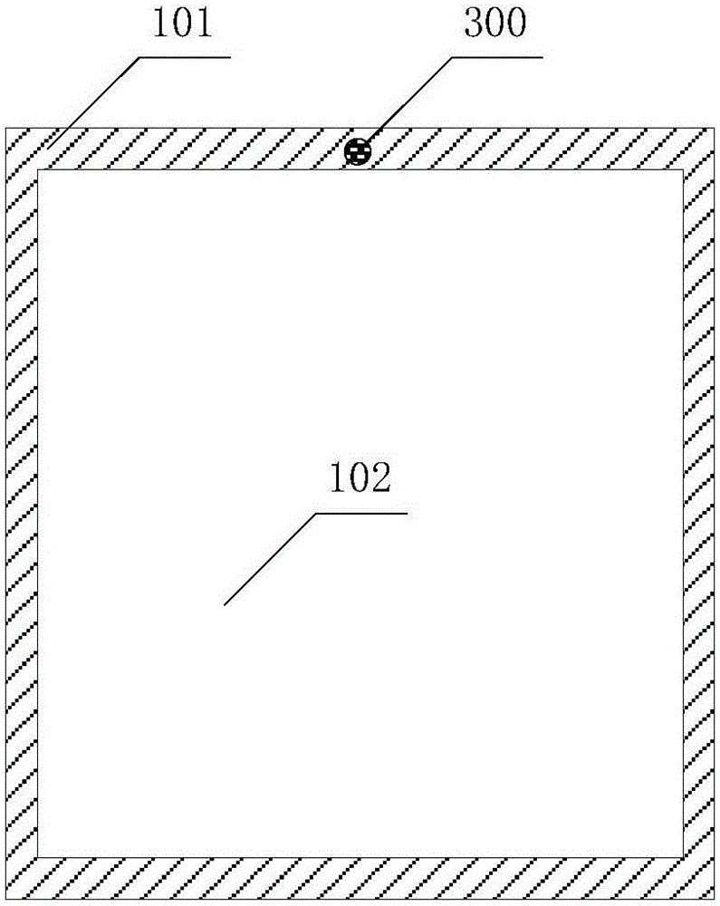
[0031] The embodiment of the present application provides a dressing mirror, such as figure 1 and figure 2 shown, including:

[0032] The transparent material cover plate 100, the surface of the transparent material cover plate 100 has a layer of semi-transparent and semi-reflective film (not attached figure 1 And attached figure 2 Shown in), including window area 102 and non-window area 101;

[0033] A touch display module 200 located on one side surfac...


PUM


Abstract

The application discloses a dressing mirror which comprises a transparent material cover board, a touch display module, an image pickup module and a processor, wherein the surface of the transparent material cover board is provided with a layer of semi-transparent and semi-reflecting membrane; the transparent material cover board comprises a window region and a non-window region; the touch display module is positioned on the surface of one side of the transparent material cover board; the image pickup module is positioned on the surface of the non-window region; the processor is connected with the touch display module and the image pickup module and is used for starting the touch display module after receiving a first startup instruction, starting the image pickup module after receiving a second startup instruction, controlling the image pickup module to shoot after receiving a shooting instruction, and displaying an image acquired by shooting. The dressing mirror can completely, conveniently and rapidly display all faces of figures of a user so as to solve the problem of difficulty of the user in seeing the complete back figure of the user in an existing dressing mirror. Furthermore, rich touch and display functions of the touch display module provide the possibility for function expansion of the dressing mirror.

Description

technical field [0001] The present application relates to the technical field of optical imaging devices, and more specifically, relates to a dressing mirror. Background technique [0002] Fitting mirrors are widely used in homes, shopping malls and public places for users to organize makeup or match clothes. But the fitting mirror in the prior art can only better present the front image of the user. When the user wants to see his back image, he needs to turn his back to the fitting mirror and try to turn his head to look towards the fitting mirror. It is difficult to present the complete back image of the user in the fitting mirror, and it is difficult for some users to turn their backs to the fitting mirror and turn their heads to look at the fitting mirror. Contents of the invention [0003] In order to solve the above technical problems, the present invention provides a fitting mirror to solve the problem that it is difficult for users to obtain their own back image i...

Claims


Application Information

Patent Timeline
Patent Type & Authority Applications(China)
IPC IPC(8): G06F3/041A47G1/02
CPCA47G1/02G06F3/0412
Inventor 张涛涛刘源张文庆林树茂李锋李志成李建华
Owner TRULY OPTO ELECTRONICS
Learn More