AI technical title is built by PatSnap AI team. It summarizes the technical point description of the patent document.
A technology for repairing platforms and transformers, applied to switchgear, electrical components, etc.
Active Publication Date: 2018-08-21
国网河南省电力公司内乡县供电公司
View PDF9 Cites 0 Cited by
Summary
Abstract
Description
Claims
Application Information
AI Technical Summary
This helps you quickly interpret patents by identifying the three key elements:
Problems solved by technology
Method used
Benefits of technology
Problems solved by technology
[0008] In view of this, the purpose of the present invention is to provide a transformer comprehensive maintenance platform for the deficiencies of the prior art, which not only solves the problem of online monitoring of the transformer cooling oil temperature, but also enables online cooling and maintenance of the transformer according to the monitoring situation. There is no need to disassemble the transformer for maintenance, which saves costs and improves work efficiency
Method used
Image
Click on the blue label to locate the original text in one second.
Reading with bidirectional positioning of images and text.
Examples
Embodiment 1
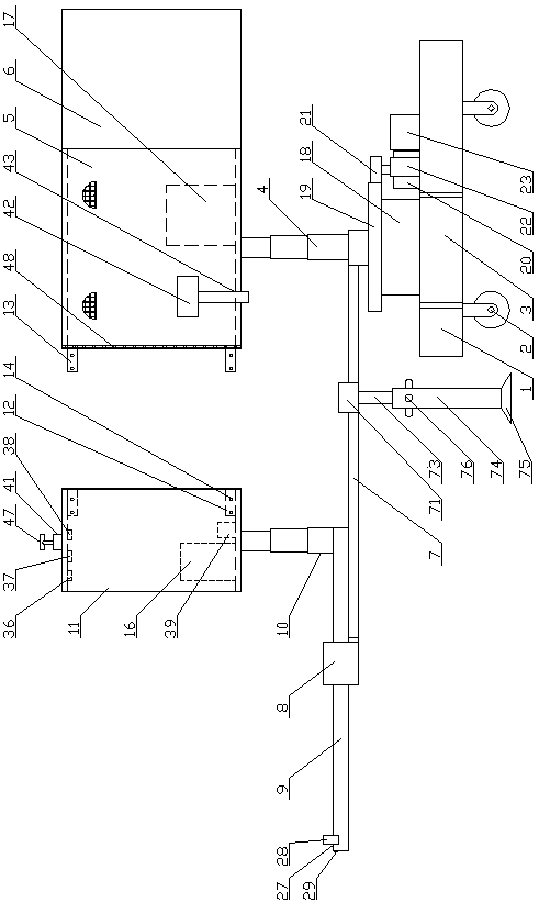
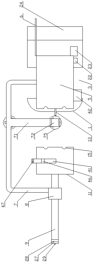
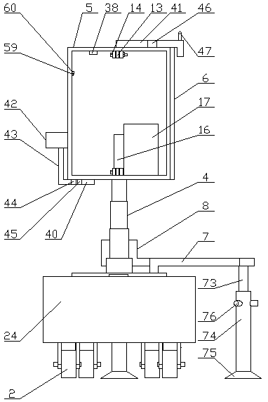
[0037] Embodiment 1: A transformer comprehensive maintenance platform, including a platform 1, a slewing mechanism arranged on the upper part of the platform 1, and a running mechanism 2 arranged at the bottom of the platform 1, and the front and rear sides of the platform 1 are provided with recesses Slot 3, the upper part of the slewing mechanism is provided with a right elevating rod 4, the top of the right elevating rod 4 is provided with a right inspection box 5, and the right end of the right inspection box 5 is rotated to install a sealed door 6, and the upper part of the slewing mechanism is close to the edge A half-frame support frame 7 is set, and a fixed sleeve 8 is arranged on the upper left end of the half-frame type support frame 7. A cantilever 9 is slidably arranged in the fixed sleeve 8, and a left elevating rod 10 is fixedly arranged on the upper surface of the right end of the cantilever 9. A left inspection box 11 is arranged on the top of the left elevating...
Embodiment 2
[0046] Embodiment 2: A transformer comprehensive maintenance platform, including a platform 1, a slewing mechanism arranged on the upper part of the platform 1, and a running mechanism 2 arranged at the bottom of the platform 1, and the front and rear sides of the platform 1 are provided with recesses Slot 3, the upper part of the slewing mechanism is provided with a right elevating rod 4, the top of the right elevating rod 4 is provided with a right inspection box 5, and the right end of the right inspection box 5 is rotated to install a sealed door 6, and the upper part of the slewing mechanism is close to the edge A half-frame support frame 7 is set, and a fixed sleeve 8 is arranged on the upper left end of the half-frame type support frame 7. A cantilever 9 is slidably arranged in the fixed sleeve 8, and a left elevating rod 10 is fixedly arranged on the upper surface of the right end of the cantilever 9. A left inspection box 11 is arranged on the top of the left elevating...
Embodiment 3
[0055] Embodiment 3: The difference between it and Embodiment 1 and Embodiment 2 is that: both the left elevating rod 10 and the right elevating rod 4 are hydraulic elevating rods.
[0056] The right end of the platform 1 is provided with a draw bar 25 , and a draw hole 26 is provided on the draw bar 25 .
[0057] An elastic layer 48 is provided on the right end surface of the left inspection box 11 and the left end surface of the right inspection box 5 .
[0058] The elastic layer 48 is made of wear-resistant rubber, and the wear-resistant rubber is composed of the following components in parts by weight: 70 parts of polyurethane rubber, 35 parts of acrylic rubber, 25 parts of nitrile rubber, 430 parts of styrene-butadiene rubber, brominated butyl 15 parts of ethylene rubber, 8 parts of polypropylene adiene siloxane, 15 parts of magnesium oxide, 20 parts of carbon black, 6 parts of urethane, 1.5 parts of polyethylene wax and 3 parts of carbon fiber. Due to the use of polyeth...
PUM
Abstract
The invention discloses a comprehensive overhaul platform of a transformer. The platform comprises a platform body, a swing mechanism arranged at the upper portion of the platform body and a walking mechanism arranged at the bottom of the platform body. The left and right sides of the platform are each provided with a groove. A right lifting rod is arranged at the upper portion of the swing mechanism. A right overhaul box is arranged on the top of the right lifting rod. A semi-frame supporting frame is arranged at the upper portion of the swing mechanism. A fixing sleeve is arranged at the end of the semi-frame supporting frame. A cantilever is arranged inside the fixing sleeve in a sliding mode. A left lifting rod is fixedly arranged on the upper surface of the right end of the cantilever. A left overhaul box is arranged on the top of the left lifting rod. A wireless oil temperature data receiving device is arranged on the bottom face of the inner side of the left overhaul box. An air conditioning device is arranged inside an overhaul chamber. An overhaul platform is arranged on the bottom face of the inner side of the right overhaul box. A transverse rod is arranged in the middle of the semi-frame supporting frame. Two auxiliary supporting mechanisms are arranged at the bottom of the transverse rod. The problem of online monitoring of the transformer oil temperature is solved, online cooling and overhauling of the transformer can be performed, overhaul can be performed without disassembling the transformer, and the cost is saved.
Description
technical field [0001] The invention relates to the technical field of power equipment monitoring, in particular to a transformer comprehensive maintenance platform. Background technique [0002] With the increase of power consumption, the demand for the capacity of distribution transformers is also continuously increasing. When the capacity of distribution transformers is 30Kv and below, the single-pole distribution transformer bench has simple structure, convenient installation, materials and land occupation. Due to the advantages of small area, distribution transformers are generally installed on a single-pole distribution transformer stand; when the capacity of distribution transformers is 50-315Kv, in order to make the distribution of distribution transformers reasonable in structure, reliable in power supply, economical in operation, It is easy to maintain and meets the requirements of safe power supply reliability and continuous and stable operation of the distributio...
Claims
Application Information
Patent Timeline
Application Date:The date an application was filed.
Publication Date:The date a patent or application was officially published.
First Publication Date:The earliest publication date of a patent with the same application number.
Issue Date:Publication date of the patent grant document.
PCT Entry Date:The Entry date of PCT National Phase.
Estimated Expiry Date:The statutory expiry date of a patent right according to the Patent Law, and it is the longest term of protection that the patent right can achieve without the termination of the patent right due to other reasons(Term extension factor has been taken into account ).
Invalid Date:Actual expiry date is based on effective date or publication date of legal transaction data of invalid patent.

