A power cable connection device
A technology for connecting equipment and power cables, which is applied in the field of power cable connection equipment, can solve problems such as line confusion, inconvenient maintenance, and intertwined cables, and achieve the effect of improving connection efficiency and facilitating classified connections
- Summary
- Abstract
- Description
- Claims
- Application Information
AI Technical Summary
Problems solved by technology
Method used
Image
Examples
Embodiment 1
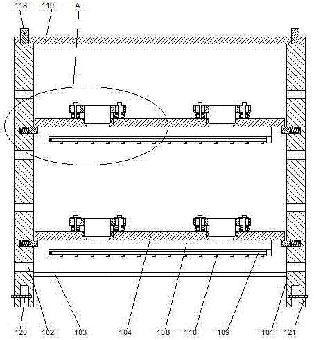
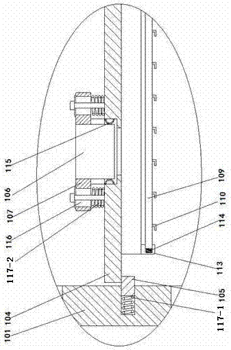
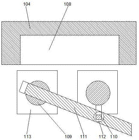
[0022] Such as Figure 1-3 As shown, a power cable connection device includes a bracket formed by two side bars 101, and wire holes 102 are respectively arranged on the side bars 101, and the upper and lower ends of the two side bars 101 respectively pass through The crossbeams 103 are connected to each other, a lifting plate 104 is arranged between the two side bars 101, a support block 105 is respectively arranged on the two side bars 101, and the two side bars 101 facing each other Counterbores arranged at intervals are respectively arranged on the end faces, and first compression springs 117-1 are respectively provided inside the counterbores, and one end of the support block 105 is inserted into the inner side of the counterbore, and the first compression spring 117-1 Under the natural state of a compression spring 117-1, the support block 105 partially protrudes from the outside of the counterbore, and the lower end surface of the lifting plate 104 is attached to the upp...
Embodiment 2
[0026] In this embodiment, in order to avoid disconnection of the connection structure when the circuit adapter board is subjected to an external force, preferably, elastic metal sheets 115 are respectively arranged on the inner walls of the installation grooves, and the elastic metal sheets 115 are facing toward the middle. The circuit adapter board 106 is a bar-shaped structure that is arched in the direction. Using the elastic metal sheet structure, the circuit adapter board is suspended relative to the installation groove. When the lifting plate is subjected to external force, under the buffering action of the elastic metal sheet, the force on the circuit adapter board can be greatly reduced, so that It is not easily damaged.
[0027] In order to enable the lifting board to move relative to the circuit adapter board, in this embodiment, preferably, the fixing ear 107 is provided with a bar-shaped hole 116, and the fixing ear 107 passes through the bar-shaped hole 116. Bol...
Embodiment 3
[0031]In this embodiment, in order to facilitate the protection of the cable adapter plate, in this embodiment, preferably, a stud 118 is provided on the upper end surface of the side bar 101, and an end is provided above the side bar 101. The cover 119, the studs 118 pass through the end cover 119 and are fixed by nuts. Using the structure of the end cover, the circuit adapter board is placed under the end cover to avoid disconnection when it is hit.
[0032] In this embodiment, a concave hole 120 corresponding to the position of the stud 118 is provided on the lower end surface of the side bar 101 . Utilize the concave holes provided on the side strips to align the two support structures longitudinally, align the concave holes on the upper side strips with the studs on the lower side strips, and make the studs on the lower side strips The studs are inserted into the concave holes on the upper side strips to realize the stacking of the upper and lower brackets.
[0033] In ...
PUM
 Abstract
Description
Claims
Application Information
 - R&D
- Intellectual Property
- Life Sciences
- Materials
- Tech Scout
- Unparalleled Data Quality
- Higher Quality Content
- 60% Fewer Hallucinations
Browse by: Latest US Patents, China's latest patents, Technical Efficacy Thesaurus, Application Domain, Technology Topic, Popular Technical Reports.
© 2025 PatSnap. All rights reserved.Legal|Privacy policy|Modern Slavery Act Transparency Statement|Sitemap|About US| Contact US: help@patsnap.com


