Multi-layer filtration gas-liquid separation device for low-pressure gas well

A gas-liquid separation device and multi-layer filtration technology, which are applied in combination devices, separation methods, dispersed particle filtration, etc., can solve the problems of blockage of the drain pipe, high production cost, complex structure of the gas-liquid separator, etc., and improve the filtration efficiency. The effect of performance, low manufacturing cost and simple structure

Inactive Publication Date: 2016-12-14
CHENGDU ZHENGSHENG ENERGY TECH DEV CO LTD
View PDF4 Cites 4 Cited by
  • Summary
  • Abstract
  • Description
  • Claims
  • Application Information

AI Technical Summary

Problems solved by technology

In the actual use process, the separation efficiency of the gas-liquid mixture is the main problem to be solved. To solve this problem, it is mostly achieved by setting complex filter elements, which makes the structure of the gas-liquid

Method used


Image

  • Multi-layer filtration gas-liquid separation device for low-pressure gas well

Examples


Example Embodiment

[0019] Example 1:

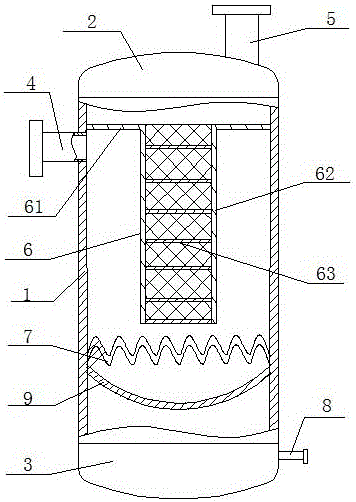
[0020] Multi-layer filter gas-liquid separation device for low-pressure gas well, such as figure 1 As shown, including a cylinder 1, the upper end of the cylinder 1 is provided with an upper end cover 2, the lower end of the cylinder 1 is provided with a lower end cover 3, the cylinder wall near the upper end of the cylinder 1 is provided with an air inlet pipe 4, and the upper end cover 2 is provided with There is an air outlet pipe 5, a liquid discharge pipe 8 is arranged on the side wall of the lower end cover 3, and a filter element 6 with a T-shaped cross section is arranged inside the cylinder body 1, and the filter element 6 includes a connecting part 61 arranged horizontally, a filter cartridge 62 arranged vertically and There are several filter discs 63 arranged in the filter cartridge 62. There are 7 filter discs 63 in this embodiment. Of course, other numbers of filter discs 63 can be designed according to actual needs. On the upper end surface,...

Example Embodiment

[0023] Example 2:

[0024] This embodiment is a further improvement on the above-mentioned embodiment, as figure 1 As shown, in the present embodiment, the filter aperture of the corrugated filter screen 7 is greater than the filter aperture of the collection filter screen 9, so that the solid impurities on the corrugated filter screen 7 can smoothly fall to the collection filter screen 9, avoiding the corrugated filter screen. Too many impurities on the net 7 will affect the gas flow at the bottom of the cylinder body 1 and reduce the bearing capacity on the corrugated filter net 7 to prevent it from being damaged. Both the collection filter screen 9 and the corrugated filter screen 7 are detachably connected to the inner wall of the cylinder body 1, which is convenient for cleaning the cylinder body 1 regularly.

Example Embodiment

[0025] Example 3:

[0026] This embodiment is a further improvement on the above-mentioned embodiment, as figure 1 As shown, in this embodiment, the upper end cap 2 and the lower end cap 3 are threadedly connected with the cylinder body 1, the connection between the upper end cap 2 and the lower end cap 3 and the cylinder body 1 is coated with sealant, and the air inlet pipe 4 is tightly connected with the cylinder body 1 , The air outlet pipe 5 is in sealing connection with the upper end cover 2, and the liquid discharge pipe 8 is in sealing connection with the lower end cover 3. The upper end cover 2 and the lower end cover 3 are threadedly connected, which is convenient for the maintenance of the present invention, and the above-mentioned connection nodes are sealed to ensure the airtightness of the present invention.


PUM


Abstract

The invention discloses a multi-layer filtration gas-liquid separation device for a low-pressure gas well, comprising a barrel; the upper end of the barrel is provided with an upper end cover, the lower end of the barrel is provided with a lower end cover, the wall of the barrel close to the upper end is provided with an intake pipe, the upper end cover is provided with an exhaust pipe, the sidewall of the lower end cover is provided with a drain pipe, a T-section filter element is disposed in the barrel and comprises a horizontally arranged connecting portion, a vertically arranged filter tube and a plurality of filter sheets arranged in the filter tube, the connecting portion connects the inner wall of the barrel to the upper end surface of the filter tube, a collection strainer bent to the lower end cover along the axis of the barrel is arranged at the bottom of the filter element in the barrel, and a corrugated strainer is mounted at the upper end of the collection strainer; by forming triple filtration through the connecting portion of the filter element, the filter tube and the multiple filter sheets, filtering performance of the device is improved; solid impurities in gas-liquid mixture are filtered doubly through the collection strainer and the corrugated strainer so as to prevent the drain pipe from being blocked.

Description

technical field [0001] The invention relates to the technical field of oil and gas exploitation equipment, in particular to a multi-layer filter gas-liquid separation device for low-pressure gas wells. Background technique [0002] In the process of oilfield exploitation, abnormal low pressure occurred in some oilfields, which brought certain difficulties to well workover. Some gas wells were exploited at low pressure, and sand was buried in the strata, which could not be cleaned up in time, which reduced the production of gas wells or even stopped production. When downhole operations are carried out without external energy supplementation, the workover fluid pollutes the formation more and more seriously, which makes the drainage period after the action continue to prolong. Therefore, it is necessary to pressurize this type of gas wells no matter during production or liquid drainage. In the prior art, a booster unit is usually used to pressurize the gas well, and the extra...

Claims


Application Information

Patent Timeline
IPC IPC(8): B01D46/00B01D46/24B01D50/00C10L3/10E21B43/34
CPCB01D46/2411E21B43/34C10L3/101C10L2290/547B01D46/56B01D50/20
Inventor 王开蓉
Owner CHENGDU ZHENGSHENG ENERGY TECH DEV CO LTD
Why Eureka
Try Eureka