Gas-liquid separation tank for single well booster set

A technology of gas-liquid separation tank and booster unit, which is applied in the direction of separation method, dispersed particle separation, gas fuel, etc., can solve the problems of complex structure and high production cost of gas-liquid separator, and achieve the protection of personnel and property safety and low manufacturing cost. Low, the effect of improving the filtration performance

Inactive Publication Date: 2016-12-14
CHENGDU ZHENGSHENG ENERGY TECH DEV CO LTD
View PDF3 Cites 0 Cited by
  • Summary
  • Abstract
  • Description
  • Claims
  • Application Information

AI Technical Summary

Problems solved by technology

In the actual use process, the separation efficiency of the gas-liquid mixture is the main problem to be solved. To solve this problem, it is mostly achieved by setting complex filter elements, which makes the structure of the gas-liquid separator complex and the production cost is high.

Method used


Image

  • Gas-liquid separation tank for single well booster set
  • Gas-liquid separation tank for single well booster set
  • Gas-liquid separation tank for single well booster set

Examples


Embodiment 1

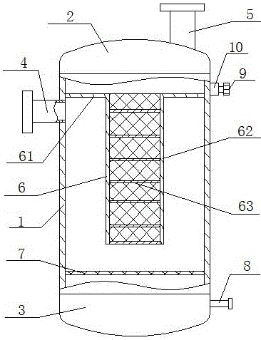
[0023] Gas-liquid separation tank for single well booster unit, such as figure 1 As shown, including a cylinder 1, the upper end of the cylinder 1 is provided with an upper end cover 2, the lower end of the cylinder 1 is provided with a lower end cover 3, the cylinder wall near the upper end of the cylinder 1 is provided with an air inlet pipe 4, and the upper end cover 3 is provided with There is an air outlet pipe 5, a liquid discharge pipe 8 is arranged on the side wall of the lower end cover 5, a pressure reducing valve 9 is arranged on the side wall of the cylinder body 1 opposite to the inlet pipe 4, and a T-shaped cross section is arranged inside the cylinder body 1. The filter element 6, the filter element 6 includes a horizontally arranged connecting portion 61, a vertically arranged filter cartridge 62 and several filter sheets 63 arranged in the filter cartridge 62. In this embodiment, the filter sheet 63 is 7 pieces, and of course it can be used according to actual ...

Embodiment 2

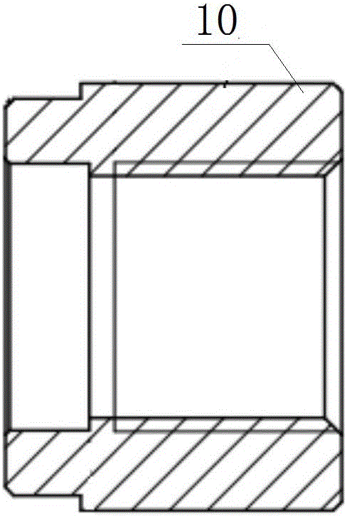
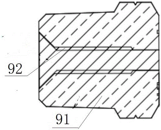
[0026] This embodiment is a further improvement on the above-mentioned embodiment, as figure 1 , figure 2 and image 3 As shown, in this embodiment, the decompression valve 9 communicates with the barrel 1 through the mounting seat 10, and the decompression valve 9 is provided with a vent hole communicating with the barrel 1 and the outside, and a plug 91 is provided in the vent hole , The plug 91 is filled with a fusible part 92 made of a temperature control material. When the flow rate of the gas-liquid mixture is too large, the gas-liquid separation is insufficient, impurities and liquid enter the exhaust pipe 5, and the exhaust pipe 5 is blocked, and the gas-liquid mixture with a large flow rate makes the internal pressure of the cylinder 1 of the present invention too large. Or due to other accidents, when the internal pressure of the cylinder 1 is too large, when the pressure exceeds a certain value, the temperature in the cylinder 1 rises, and the fusible part 92 in ...

Embodiment 3

[0028] This embodiment is a further improvement on the above-mentioned embodiment, as figure 1 As shown, in this embodiment, a filter screen 7 is detachably arranged below the filter element 6 in the cylinder body 1 to filter impurities in the gas-liquid mixture, so as to facilitate further processing of the liquid part in the gas-liquid mixture. The filter screen 7 is detachably connected with the inner wall of the cylinder body 1, which is convenient for cleaning the cylinder body 1 regularly.


PUM


Abstract

The invention discloses a gas-liquid separation tank for a single well booster set. The gas-liquid separation tank comprises a cylinder, wherein an upper end cap is arranged at the upper end of the cylinder, a lower end cap is arranged at the lower end of the cylinder, a gas inlet pipe is arranged on the cylindrical wall, close to the upper end, of the cylinder, a gas outlet pipe is arranged on the upper end cap, a liquid discharging pipe is arranged on the side wall of the lower end cap, a pressure reducing valve is arranged on the side wall, on the side opposite to the gas inlet pipe, of the cylinder, a filter element with a T-shaped cross section is arranged in the cylinder and comprises a horizontally arranged connecting portion, a vertically arranged filter cartridge and a plurality of filter pieces arranged in the filter cartridge, and the connecting portion is connected with the inner wall of the cylinder and the upper end face of the filter cartridge. The connecting portion of the filter element, the filter cartridge and multiple filter pieces form three-stage filtration, liquid components in a gas-liquid mixture can be filtered and settle to the most degree, the filtering performance of the gas-liquid separation tank is improved, and the gas-liquid separation tank is simple in structure and low in manufacturing cost.

Description

technical field [0001] The invention relates to the technical field of oil and gas exploitation equipment, in particular to a gas-liquid separation tank used for a single well booster unit. Background technique [0002] In the process of oilfield exploitation, abnormal low pressure occurred in some oilfields, which brought certain difficulties to well workover. Some gas wells were exploited at low pressure, and sand was buried in the strata, which could not be cleaned up in time, which reduced the production of gas wells or even stopped production. When downhole operations are carried out without external energy supplementation, the workover fluid pollutes the formation more and more seriously, which makes the drainage period after the action continue to prolong. Therefore, it is necessary to pressurize this type of gas wells no matter during production or liquid drainage. In the prior art, a booster unit is usually used to pressurize the gas well, and the extracted natural...

Claims


Application Information

Patent Timeline
IPC IPC(8): B01D50/00B01D46/00B01D46/12B01D46/24B01D46/42C10L3/10E21B43/34
CPCB01D46/0002B01D46/0008B01D46/0087B01D46/12B01D46/2411B01D46/4272E21B43/34C10L3/10B01D2267/40B01D46/56B01D50/20
Inventor 王开蓉
Owner CHENGDU ZHENGSHENG ENERGY TECH DEV CO LTD
Why Eureka
Try Eureka