Art knife structure capable of clamping blade

A utility knife and blade technology, applied in metal processing, artist's hand tools, decorative art, etc., can solve problems such as shaking and the inability of utility knives to cut accurately, and achieve the effect of firm fixation, precise cutting, and improved stability

Pending Publication Date: 2016-12-14
顺德工业(江苏)有限公司
View PDF0 Cites 4 Cited by
  • Summary
  • Abstract
  • Description
  • Claims
  • Application Information

AI Technical Summary

Problems solved by technology

[0002] During the use of the utility knife, the position of the blade needs to be locked. The existing blade position locking structure is to clamp the regulator through the locking tooth groove. However, in the actual use process, the width of the blade groove is generally larger than the width of the blade, and the blade groove The height of the blade is also greater than the thickness of the blade, and the blade is easily shaken in the groove during actual use, making it impossible for the utility knife to perform precise cutting

Method used


Image

  • Art knife structure capable of clamping blade
  • Art knife structure capable of clamping blade
  • Art knife structure capable of clamping blade

Examples


Embodiment Construction

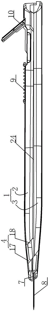
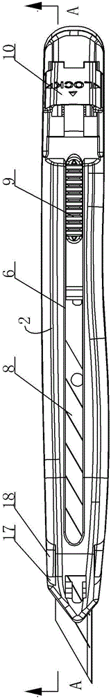
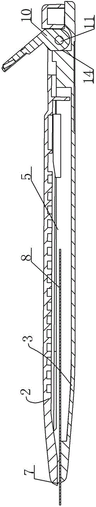
[0029] A utility knife structure capable of clamping blades, see Figure 1 to Figure 9 , which includes:

[0030] A knife body 1, it comprises the first knife body 2, the second knife body 3, the first knife body 2 is positioned at the relative top of the second knife body 3, the front end of the first knife body 2, the front part of the second knife body 3 buckle each other and form a relatively sliding Inclined surface limiting structure 4, the blade guide groove 5 is formed in the blade body after the combination of the first blade body 2 and the second blade body 3, the top of the blade guide groove 5 is provided with a blade driving guide groove 6, and the blade driving guide groove 6 is parallel to the blade guide Groove 5, the front end of knife body is that the front end goes out knife edge 7;

[0031] A blade 8; the blade 8 is located in the blade guide groove 5;

[0032] A regulator 9, the regulator 9 is used to block the blade 8 and drive the blade 8 to move forwa...


PUM


Abstract

The invention provides an art knife structure capable of clamping a blade. The blade can be clamped so as not to shake during a use process, so that the accurate cutting is realized, the blade can be firmly fixed, and the stability in using the blade is improved. The art knife structure capable of clamping the blade comprises a knife body comprising a first knife body and a second knife body, the blade, an adjuster, a locking block and a spring; the first knife body is located relatively above the second knife body; the front end of the first knife body and the front part of the second knife body are mutually fastened to form a slope limiting structure capable of relatively sliding; the blade is located in a blade guiding slot; the adjuster is used for clamping the blade; the locking block is fixedly arranged on the rear part of the first knife body through a rotary shaft; a spring installation cavity is reserved between front positions, of the locking block, on which the first knife body and the second knife body are located; the front end of the spring is arranged on the first knife body in an ejecting way; and the rear end of the spring is arranged on the second knife body in an ejecting way.

Description

technical field [0001] The invention relates to the technical field of utility knife structures, in particular to a utility knife structure capable of clamping blades. Background technique [0002] During the use of the utility knife, the position of the blade needs to be locked. The existing blade position locking structure is to clamp the regulator through the locking tooth groove. However, in the actual use process, the width of the blade groove is generally larger than the width of the blade, and the blade groove The height of the knife is also greater than the thickness of the blade, and the blade is very easy to shake in the knife groove during actual use, making the utility knife unable to perform precise cutting. Contents of the invention [0003] In view of the above problems, the present invention provides a utility knife structure capable of clamping the blade, which can clamp the blade so that the blade does not shake during use, thereby achieving precise cutti...

Claims


Application Information

Patent Timeline
Patent Type & Authority Applications(China)
IPC IPC(8): B26B1/08B44B11/00
CPCB26B1/08B44B11/00
Inventor 杜兵峰
Owner 顺德工业(江苏)有限公司
Why Eureka
Try Eureka