Power penetrometer capable of automatically taking energy correction and dynamic responses into consideration

A technology of dynamic response and penetrometer, which is applied in the fields of on-site foundation soil survey, construction, and basic structure engineering, etc., which can solve the problems of ineffective detection of the properties of hard soil layers penetrated, reduction of engineering application value of soil parameters, and inability to represent Problems such as the original state index of the soil layer can be reduced to reduce the influence of temperature and bending effects, shorten the evaluation period, and reduce the cost of investigation

Active Publication Date: 2016-12-14
SOUTHEAST UNIV
View PDF5 Cites 6 Cited by
  • Summary
  • Abstract
  • Description
  • Claims
  • Application Information

AI Technical Summary

Problems solved by technology

Existing dynamic penetration tests such as standard penetration test (SPT), dynamic penetration testing (DCP) penetration mechanism and design theory still have many ambiguities, and the theory is far behind the practice. The evaluation of the dynamic response of the cone tip 1. There is little research on the conversion of hammering energy, which results in a waste of energy. For the investigation of hard soil sites, the properties of penetrating hard soil layers cannot be effectively detected.
[0003] The laboratory test method relies on sampling technology, so it is affected by sampling disturbance and size effect, and the reliability of the given survey design parameters is not strong
The physical and mechanical property indexes of the measured soil often cannot represent the original state index of the soil layer, which greatly reduces the engineering application value of the soil parameters

Method used


Image

  • Power penetrometer capable of automatically taking energy correction and dynamic responses into consideration
  • Power penetrometer capable of automatically taking energy correction and dynamic responses into consideration

Examples


Embodiment Construction

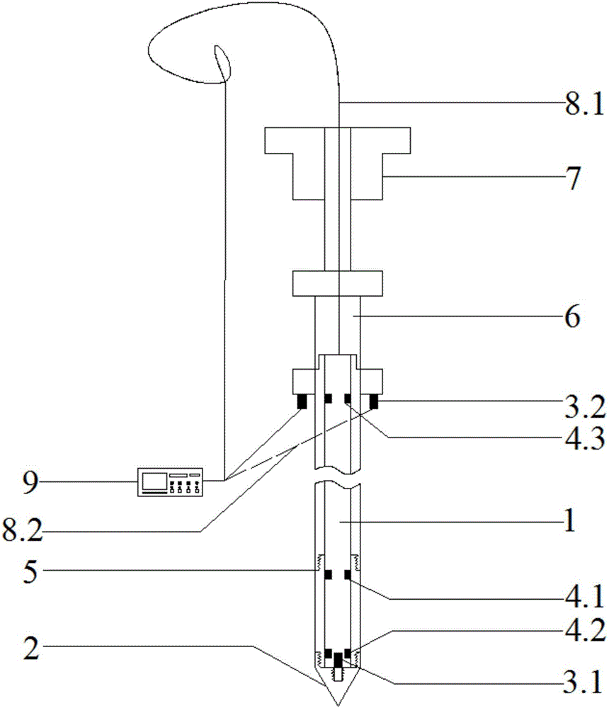
[0013] A power penetrometer that automatically considers energy correction and dynamic response of the present invention includes that the penetrometer includes a drop weight 7, a stabilized fin 6, and a probe rod 1 in order from top to bottom; wherein, the upper end of the probe rod 1 and the stabilized fin 6 are connected, the third strain gauge 4.3 is symmetrically installed on the inner wall of the upper end of the probe rod 1, and the second acceleration sensor 3.2 is symmetrically arranged at the lower end of the stabilizer fin 6. The first acceleration sensor 3.1 and the second strain gauge 4.2 are arranged inside, the friction sleeve 5 is arranged outside the probe rod 1, and the first strain gauge 4.1 is arranged on the inner wall of the top of the friction sleeve 5; The drop hammer 7, the electrical signals of the sensors of the penetrometer are transmitted to the data acquisition analyzer 9 by the coaxial cable 8.1 and the signal cable 8.2.

[0014] The outer diamet...


PUM


Abstract

The invention discloses a power penetrometer capable of automatically taking energy correction and dynamic responses into consideration. The power penetrometer sequentially comprises a drop hammer (7), a stabilizing tail vane (6) and a feeler lever (1) from top to bottom, wherein the upper end of the feeler lever (1) is connected with the stabilizing tail vane (6), third strainometers (4.3) are symmetrically mounted on the inner wall of the upper end of the feeler lever (1), second acceleration sensors (3.2) are symmetrically arranged at the lower end of the stabilizing tail vane (6), a conical tip (2) is arranged at the lowermost end of the feeler lever (1), a first acceleration sensor (3.1) and second strainometers (4.2) are arranged in the portion, above the conical tip (2), inside the feeler lever (1), a friction sleeve (5) is arranged outside the feeler lever (1), and first strainometers (4.1) are arranged on the inner wall of the top of the friction sleeve (5); and the drop hammer (7) which can be automatically triggered to drop is arranged on the upper portion of the stabilizing tail vane (6), and electric signals of all sensors of the penetrometer are transmitted to a data acquisition and analysis instrument (9) through a coaxial cable (8.1) and a signal cable (8.2). The power penetrometer can evaluate dynamic responses and detect the strength of a soil body and has the characteristics of being in situ, multifunctional, automatic and the like.

Description

technical field [0001] The invention relates to a dynamic penetrometer which automatically considers energy correction and dynamic response, and belongs to a dynamic penetrometer in the field of in-situ testing in the field of geotechnical engineering. Background technique [0002] The dynamic penetration test is an in-situ test method used in geotechnical engineering investigation. It uses a drop hammer of a certain quality to drive a standard conical probe into the soil layer with a free fall distance of a certain height. The difficulty of penetration is used to determine the nature of the soil layer. From the basic principle of the dynamic penetrating test, the key issue of the dynamic penetrating test is the transmission and transformation of the axial impact force and hammer energy in the probe rod after the probe rod is impacted by the falling weight. Existing dynamic penetration tests such as standard penetration test (SPT), dynamic penetration testing (DCP) penetrat...

Claims


Application Information

Patent Timeline
Patent Type & Authority Applications(China)
IPC IPC(8): E02D1/02
CPCE02D1/022
Inventor 段伟蔡国军
Owner SOUTHEAST UNIV
Why Eureka
Try Eureka